LONGER RAY5 10W · Volume 3
Running the RAY5 — software, focus, and the Roller in depth
3.1 The software chain, from art to G-code
Nothing happens on the RAY5 until a piece of artwork has been turned into a stream of coordinated motion and power commands. Two programs dominate the diode-laser world and both drive the RAY5: LaserGRBL and LightBurn. LaserGRBL is free, Windows-only, and pleasantly direct — it imports an image, lets the operator set speed and power and an engraving mode, and streams the resulting G-code to the machine over USB. It is an excellent way to learn the machine and perfectly adequate for straightforward raster engraving. LightBurn is paid, cross-platform, and the tool most serious users settle on; it is a proper layout and vector environment as well as a laser controller, with far better handling of vector cutting, multiple layers at different speeds and powers, image processing, and — importantly for this volume — first-class rotary support. Both speak GRBL, so both connect to the RAY5’s ESP32 controller natively, and work prepared in either can also be exported to the microSD card for offline running from the touchscreen.
LightBurn earns its keep on the RAY5 in a handful of specific ways worth naming, because they are the features an owner reaches for daily. Layers let a single file carry, say, a raster-engraved graphic and a vector cut outline that run at completely different speeds and powers in one job, executed in a controlled order. The image-processing panel adjusts brightness, contrast, and gamma and chooses the halftone or error-diffusion mode before a photo is ever sent to the machine, which is where most of the quality of a photo engraving is actually won. The built-in material-test generator burns the very grids described later in this volume without hand-drawing them. And the rotary dialog, discussed at length below, is what makes the Roller usable at all. LaserGRBL covers the essentials for free and is the better place to start, but a maker who engraves regularly generally graduates to LightBurn for these tools.
Whichever program is used, the job passes through the same conceptual stages. The design is placed and sized on a virtual bed that mirrors the machine’s 400 by 400 mm area. Each element is assigned a mode — engrave (raster) or cut/score (vector) — and a speed and power. The software then generates G-code: a long list of moves, each tagged with a laser power, that the controller will execute line by line. Understanding the two fundamental modes, and how power maps to result, is most of what it takes to use the machine well.
3.2 Raster, vector, dithering, and photos
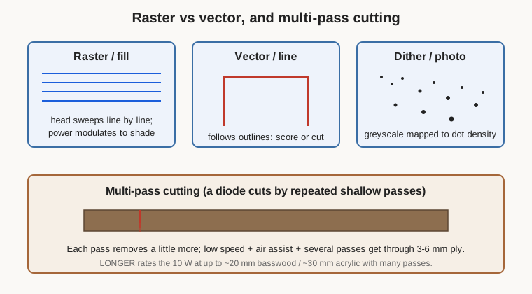
Raster engraving sweeps the head back and forth across an area like an inkjet printhead, turning the laser on and modulating its power point by point to lay down a filled image. This is how solid graphics, filled text, and photographs are burned. The controlling variables are speed, maximum power, and line interval (how far apart the sweep lines sit, which sets vertical resolution); finer intervals give smoother results at the cost of time. Vector engraving, by contrast, follows the outlines of shapes rather than filling them — the head traces a path — and is used for line art, outline text, scoring fold lines, and cutting. A vector operation at low power scores a visible line; the same path at high power and slow speed, repeated over several passes, cuts through.
Photographs are a special case of raster and the RAY5’s fine 0.06 mm spot makes it good at them. A continuous-tone photo has to be reduced to what a laser can actually produce — a pattern of burned and unburned spots — and the two common approaches are grayscale power modulation, where the laser’s power tracks the image’s brightness, and dithering, where the image is converted to a field of same-power dots whose density varies to suggest tone, the way a newspaper halftone works. Dithering (and its more sophisticated cousins like Jarvis and Stucki error-diffusion, offered in LightBurn) often gives the most reliable results on wood and other organics because it sidesteps the material’s non-linear response to power. Good photo engraving rewards patience: the material matters enormously, the image usually needs contrast and sharpening adjustments before it is sent, and a test on scrap of the same stock is always worth the ten minutes it costs.
3.3 Focusing, framing, and finding settings
Because the module is fixed focus, focusing is a mechanical ritual rather than a software step, and it is done the same way every time: rest the supplied spacer between the nozzle and the workpiece surface, loosen the module on its Z mount, lower it until it just meets the spacer, retighten, and remove the spacer. That sets the one correct nozzle-to-work air gap at which the beam reaches its tightest spot. Get it wrong and the spot is fat and weak; every symptom of a “low-power” laser is, as often as not, simply a focus that is off. On stepped or thick work, focus is set to the surface that matters most.
With focus set, framing positions the job. The machine traces the design’s bounding box at low power so the operator can see exactly where it will land and shift the workpiece accordingly — indispensable on expensive or oddly shaped stock. Then comes dialing in settings, which on any laser is best done empirically rather than from a table. The standard technique is a material test: a grid burned onto scrap of the exact material, stepping speed along one axis and power along the other, so the operator can read off the combination that gives the wanted darkness, depth, or clean cut. LightBurn has a built-in material-test generator for exactly this. Settings that work on one wood will be wrong on another, and even different boards of the same species vary, so the test grid is not a beginner’s crutch but a permanent part of good practice. Air assist, where fitted, is switched on for cutting and heavy engraving to keep smoke out of the beam and edges clean; the previous volume covered the hardware.
A worked example makes the settings process concrete. Suppose the task is a filled logo on a slat of birch plywood. The operator focuses with the spacer, mounts the slat, and burns a quick test grid on an offcut: five speeds down the page, five powers across, each cell a small filled square. Reading the grid, a cell that is dark and evenly toned without deep charring or a scorched halo marks the target — say 4000 mm/min at 40 % power with a 0.10 mm line interval. Those numbers go into the real job. If the result is too pale, the fix is more power or less speed; if it is charred and fuzzy at the edges, less power or more speed, and air assist to clear the smoke. The same discipline scales to any material: the grid is the map, and the operator reads their route off it rather than guessing. Keeping a notebook or a labelled board of proven settings per material turns each test into a permanent asset rather than a repeated cost.
Cutting on a diode is a game of passes. Rather than trying to slice through in one slow, scorching pass, the operator runs the cut line several times at a moderate speed and full power, each pass deepening the kerf. Thin plywood and acrylic yield in a handful of passes with air assist; thicker stock takes many more, and there is a point of diminishing returns beyond which the CO2 laser is simply the right tool. A honeycomb bed or a set of raised standoffs under the work helps by letting the beam exit cleanly and air circulate, and by keeping the burning underside off the frame.
3.4 The Roller — what it is and how it changes the machine
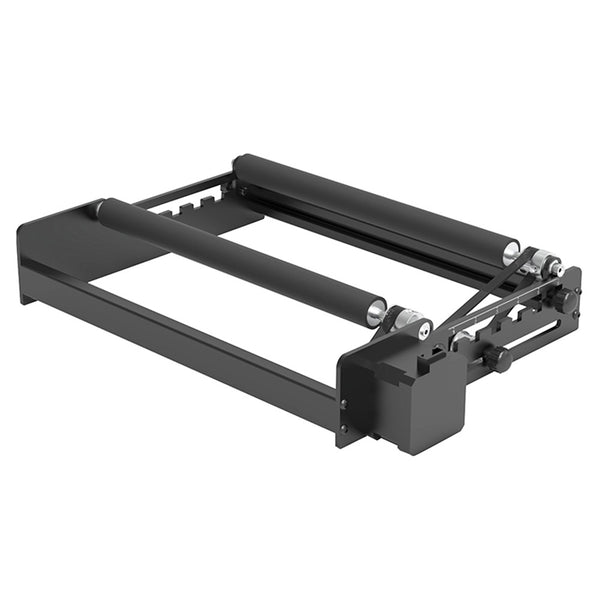
The Roller is a rotary attachment that converts the RAY5 from a flat-work engraver into one that can wrap a design around a cylinder. Mechanically it is a compact steel frame carrying two parallel shafts fitted with high-friction rubber wheels — LONGER specifies a fairly hard 70A anti-slip rubber — one shaft driven by a stepper motor and the other idling. A cylindrical object, a tumbler or a glass or a can, is simply laid across the two shafts; the driven shaft turns it. The attachment arrives essentially pre-assembled and is, in LONGER’s words, plug-and-play: it connects to the machine by the same cable and connector the Y-axis motor used.
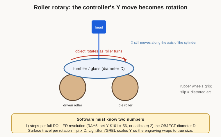
That connector detail is the whole trick. When the Roller is plugged into the Y-axis output, the controller does not know anything has changed — it still believes it is commanding a Y motor to move the gantry in and out. But that motion now rotates the workpiece instead. So the machine’s Y axis becomes rotation, while the X axis continues to move the laser head along the length of the cylinder. A two-dimensional design in the software is thereby painted onto a curved surface: X runs along the barrel of the glass, and “Y” wraps it around the circumference. The head itself stays put in Y and only its X carriage and the rotating object move.
The Roller’s rubber wheels are spaced by a manual, multi-position adjustment — slide the shaft and lock a thumbscrew — so the cradle can hold a range of diameters, roughly from small pens up toward 200 mm at the large end, with the practical working range for tumblers and glasses comfortably inside that. Because a laid-on cylinder sits higher than the flat bed, the kit includes risers to lift the rest of the machine so the fixed-focus module can still reach its correct air gap to the top of the curved surface.
3.5 Setting the Roller up in software
Getting an undistorted engraving from the Roller requires telling the software how rotation maps to surface distance, and this is where the two numbers introduced in the first volume come in. The first is a property of the attachment: how many motor steps correspond to one full revolution of the roller — not one revolution of the object. LightBurn’s rotary dialog asks for this directly, and for the RAY5 specifically LONGER’s guidance is to set the Y-axis steps-per-millimetre parameter (GRBL’s $101) to a value of 56 for the roller, or to calibrate it: command a known rotation, measure how far the roller actually turned, and correct the number until commanded and actual agree. The second number is a property of the job: the diameter of the object currently on the rollers. LightBurn takes either the diameter or the circumference and computes the other, then scales the rotary axis so that a design of a given width comes out that same width when wrapped around the curved surface. Enter the wrong diameter and the art comes out proportionally stretched or squashed around the circumference — the single most common rotary mistake.
The mechanical setup follows a consistent recipe. Plug the Roller into the Y connector and fit the risers. Lay the object on the wheels and adjust their spacing so it sits level and centred, its axis parallel to the machine’s X travel. Set the software into rotary mode, choose the roller type, enter the steps-per-revolution and the object’s measured diameter, and set focus to the top of the object’s curve with the spacer. Frame the job — in rotary mode framing will rock the object back and forth and run the head along X to show the engraving envelope — and adjust position until the design sits where wanted on the barrel. Then run at settings found, as always, from a test on a similar surface. Powder-coated and painted tumblers, anodized bottles, bare stainless, and wood all behave differently, and stainless and bare metal in particular usually want a marking spray, covered in the materials volume.
3.6 Roller gotchas — slippage, taper, and balance
Three practical problems account for most spoiled rotary jobs. The first is slippage: if the object does not turn in perfect lockstep with the rollers, the engraving smears or doubles where rotation and commanded motion drift apart. Slippage comes from a workpiece too light to grip the rubber, from grease or condensation on the surface, or from a load unbalanced enough to slip under its own momentum during the quick reversals of a raster fill. The remedies are to keep the wheels and the workpiece clean and dry, to run rotary engravings at gentler speeds and accelerations than flat work so the object is never asked to start or stop violently, and, for very light objects, to add a little mass or use the attachment’s end supports where fitted.
The second is taper. Many drinking glasses and tumblers are not true cylinders — they widen or narrow along their length. A rotary attachment assumes a single diameter, so on a tapered vessel the engraving is at correct scale only where the actual diameter matches the number entered, and it drifts out of focus toward the ends as the surface rises or falls away from the fixed-focus lens. The workable approaches are to keep designs within a short length near the diameter that was entered, to shim the narrow end up so the engraved band runs level and stays in focus, or to accept that a strongly tapered glass is not an ideal candidate. The third problem is simply balance and levelling: an object whose axis is not parallel to the X travel will engrave a design that spirals rather than wraps straight, and one that is not centred between the wheels can walk sideways as it turns. A minute spent getting the object sitting square, level, and snug repays itself many times over. With those three watched, the Roller is a reliable and genuinely rewarding accessory — it is, for many owners, the single feature that justifies the machine, turning plain tumblers and glasses into personalized pieces the flat bed could never touch.
Comments (0)