60 W CO2 Laser · Volume 2
The Machine in Detail — Tube, Optics, Motion, and Control
2.1 Opening the cabinet
A large-format CO2 laser looks, from the outside, like a big metal box with a lid — closer to a chest freezer than to a machine tool. Lift the lid and the logic of the thing becomes clear. Along one wall, usually the back, runs a long glass tube: the laser itself. Above the bed rides a bridge that carries a small head back and forth. Tucked into a side compartment are the electronics, and threaded through the whole structure are water lines, an air line, and a fat exhaust duct. This volume walks that anatomy part by part, following the energy from where the beam is born to where it meets the material. The support systems — cooling, air, exhaust, electrical — get their own volume; here the focus is the machine itself.
2.2 The glass CO2 laser tube
The beam begins in the laser tube, and everything else in the machine exists to power it, cool it, aim it, or move the work under it. In a machine of this class the tube is a sealed glass CO2 tube: a long, slender cylinder of borosilicate glass, filled with a low-pressure mixture that is mostly carbon dioxide with helium and nitrogen added to help it lase efficiently. For a 60 watt rating the tube is typically around 1.2 to 1.25 metres long and 50 to 60 millimetres in diameter — a genuinely large glass object, which is one reason these machines are so big and why the tube is the most fragile expensive part in the whole system.
The tube is DC-excited, meaning the beam is produced by driving a steady high-voltage direct current through the gas from one end of the tube to the other. An electrode at each end connects to the power supply; when the supply strikes an arc through the gas, the carbon dioxide molecules are pumped into an excited state and then dump their energy as coherent 10.6 micrometre infrared light. A partially reflective mirror on the tube’s output end lets a fraction of that light escape as the usable beam while the rest bounces back and forth inside to keep the process going. This is a sealed tube — the gas is not replenished — which is why tubes wear out and are treated as consumables with a finite life, a topic returned to in the reference volume.
Wrapped around the discharge region is a water jacket: an outer glass sleeve with cool water flowing through it. This is not optional plumbing. The discharge dumps a great deal of heat into the glass, and without a continuous flow of cooling water the tube overheats and the glass cracks — often within seconds of firing dry. The cooling loop is important enough that it, and the flow-sensing interlock that guards it, are covered fully in the next volume. For now, the essential fact is that the tube and its cooling are inseparable: a CO2 tube that fires without water is a CO2 tube that is about to become scrap.
2.3 The high-voltage laser power supply
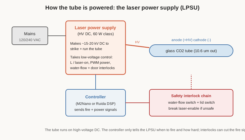
The tube is fed by a dedicated laser power supply, usually abbreviated LPSU. It takes ordinary mains electricity and produces the very high DC voltage — on the order of 15 to 20 kilovolts — needed to strike and sustain the discharge in the tube. A 60 watt machine uses an LPSU sized to match; these are commodity items, sold by tube power rating, and are themselves a common failure and upgrade point.
Two things about the LPSU deserve emphasis. First, the voltages involved are lethal, and they persist in the supply’s capacitors after power is removed. The high-voltage side of a CO2 laser is a genuine electrocution hazard, not a nuisance shock, and it is the reason the machine’s electrical bay is treated with the same caution as mains wiring in the safety material. Second, the LPSU does not decide on its own how hard to fire. It has low-voltage control inputs, and it takes its orders from the machine’s controller: a signal that says fire now, and a signal — typically a PWM (pulse-width-modulated) waveform — that sets how much power. Crucially, the LPSU also has interlock inputs: connections that will refuse to let the laser fire unless conditions are safe, most importantly the cooling-water flow switch and the lid switch. A correctly wired machine simply cannot fire the tube with the water off or the lid open, because the LPSU’s enable line is broken.
2.4 The flying-optics beam path: three mirrors and a lens
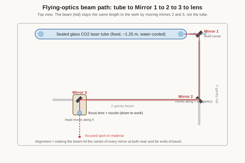
Here is the signature idea of the whole machine. The tube is fixed — it is long, heavy, fragile, and tethered to water and high voltage, so it cannot move. Yet the cutting point must be able to reach every square millimetre of a large bed. The solution, shared by nearly every machine in this class, is called flying optics: the beam is steered by mirrors so that a small, light head can fly around the bed while the beam always finds it.
Follow the beam. It leaves the output end of the tube as a straight horizontal pencil of invisible light and strikes Mirror 1, a small mirror fixed in the corner of the machine near the tube. Mirror 1 turns the beam ninety degrees and sends it along the machine to Mirror 2, which is mounted on the moving gantry — the bridge that travels forward and back across the bed (the Y axis). Because Mirror 2 rides on the gantry, it catches the beam wherever the gantry happens to be. Mirror 2 turns the beam ninety degrees again, sending it along the length of the gantry beam to Mirror 3, which lives in the cutting head that slides side to side along the gantry (the X axis). Mirror 3 makes the final turn, bending the beam straight down, and sends it through the focusing lens in the head. The lens concentrates the beam to a tiny, intense point at a fixed distance below it — the focal point — and that point is where cutting happens.
The elegance of the arrangement is that no matter where the head is, the total path length from tube to work stays effectively constant, and a single fixed tube serves the entire bed. The catch is that it only works if all three mirrors are precisely aimed. If any mirror is off, the beam drifts across the machine as the head moves, hits the mirrors off-centre, loses power, and eventually clips a mount and stops reaching the head at all. Keeping the three mirrors aligned is therefore a core maintenance ritual, covered in the reference volume.
2.5 The cutting head and lens
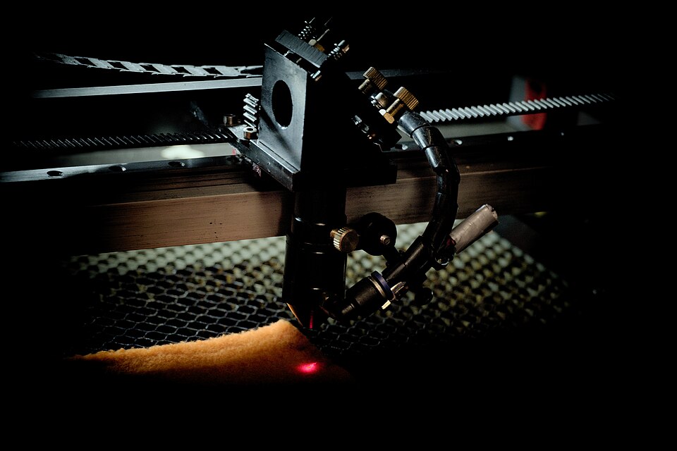
The cutting head is where the beam becomes useful. It holds Mirror 3, the focusing lens, and the air-assist nozzle, all in a compact assembly at the end of the moving gantry. The lens is typically a zinc-selenide (ZnSe) lens — a special infrared-transmitting optic, faintly yellow, that focuses 10.6 micrometre light the way a glass lens focuses visible light. Its focal length sets how far below the lens the beam comes to its sharpest point and how tight that point is; a shorter focal length gives a finer spot for detailed engraving, a longer one gives more depth of focus for cutting thick material. Getting the material surface exactly at the focal point — focusing — is one of the most important things an operator does before a job, and it is why the head’s height relative to the work is adjustable.
Surrounding the lens is the nozzle, a cone that both directs a jet of assist air down onto the cut and shields the lens from smoke and debris. A clean lens is essential: any soot or spatter on it absorbs the beam, heats up, and quickly ruins the lens while robbing the cut of power. The head is also the part most exposed to damage — it is where fires start, where debris flies, and where a crash into a tall workpiece can knock a mirror out of alignment — so it earns careful attention.
2.6 The X/Y gantry and stepper motion
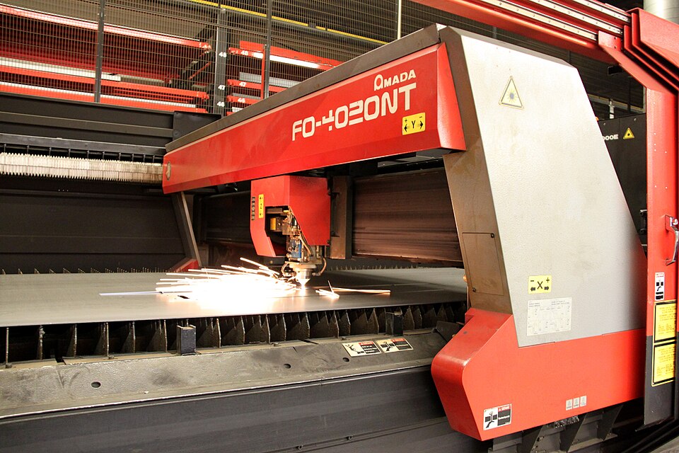
The head’s motion comes from a Cartesian gantry, the same basic architecture as a 3D printer or CNC router. Two axes do the work: the X axis slides the head left and right along the gantry beam, and the Y axis rolls the whole gantry forward and back along rails at the sides of the bed. Together they place the focused point anywhere over the working area.
Motion is driven by stepper motors — motors that rotate in fixed, precise increments rather than spinning freely — turning toothed belts that pull the head and gantry along linear rails or wheels. Steppers are the natural choice here because the controller can command an exact number of steps and trust the motor to move exactly that far, without needing position feedback, so long as nothing stalls or crashes. The belts, rails, and wheels are ordinary mechanical parts that need occasional tensioning and cleaning; because the moving mass is only a light head and a bridge (the heavy tube stays put), these machines can move quickly, which matters for raster engraving where the head sweeps back and forth thousands of times. On a large-format machine the longer belts and rails have a little more flex and stretch than a small machine, one of several reasons owners upgrade the motion components and bed as part of a modification program.
2.7 The controller: M2Nano versus Ruida DSP
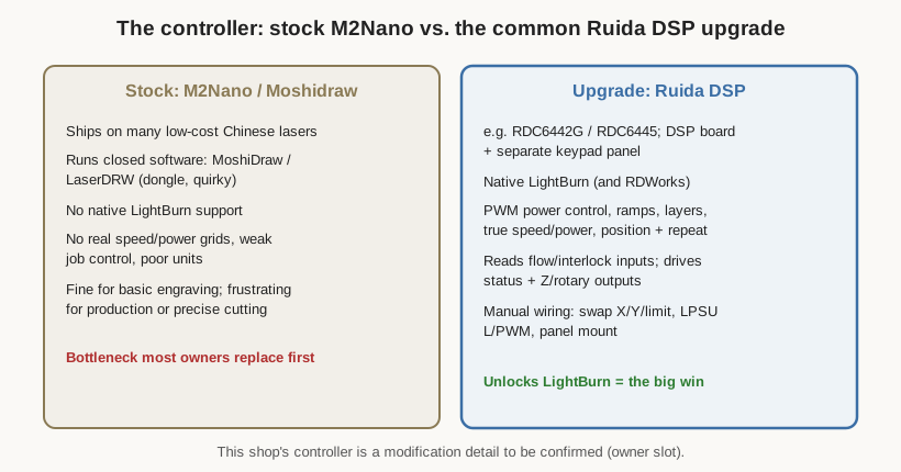
If the tube is the machine’s muscle, the controller is its brain, and it is the part that most defines how the machine feels to use. The controller reads the job, works out the toolpaths, generates the precisely-timed step-and-direction pulses for the motors, and tells the LPSU when and how hard to fire — all in real time, coordinating motion and beam so the power tracks the speed through corners and curves.
Many low-cost Chinese lasers ship with an old, closed controller — the M2Nano board, driven by Moshidraw or LaserDRW software (sometimes gated behind a hardware dongle). It works, after a fashion, but it is a frustrating platform: quirky software, poor units, no real speed-and-power control, weak job management, and — decisively — no support for modern laser software. The near-universal upgrade is a Ruida DSP controller (models such as the RDC6442G or RDC6445), a proper digital-signal-processor board paired with a keypad panel. The Ruida is a serious motion controller: it does true PWM power control, smooth acceleration ramps, layered jobs with independent settings, position and repeat functions, and it reads the safety interlock inputs and drives status outputs. Above all, it unlocks LightBurn, the software the whole community has standardised on, which is the subject of the next volume’s second half.
Whether this particular machine still wears its stock controller or has received the Ruida upgrade is an owner-build detail left as a slot. The general point stands regardless: the controller is the single biggest determinant of how capable and pleasant a large-format Chinese laser is to run, and it is the first thing most owners change.
2.8 The bed, the Z axis, and the control panel
Beneath the head is the bed, where the work sits. The best beds for cutting are honeycomb or blade tables: an aluminium honeycomb panel, or a grid of thin steel blades, that supports the material on a minimal contact area while letting smoke, debris, and the spent beam pass through instead of reflecting back up to scorch the underside of the cut. A honeycomb bed also lets the assist air and exhaust move freely under the work. Stock machines sometimes ship with a cruder slat or flat bed, and a proper honeycomb table is a common upgrade.
Many machines add a Z axis: the ability to raise and lower the bed (or the head) so the material surface can be brought to the lens’s focal point regardless of the material’s thickness. On simpler machines this is a manual adjustment; better ones motorise it and let the software set focus automatically. A motorised Z also enables tricks like ramping focus through a thick cut. The control panel — the keypad and small display mounted on the cabinet — is the machine’s standalone face: it lets the operator jog the head, set the origin, start and pause and stop a job, and read status, all without a computer once a file has been sent. On a Ruida machine the panel is part of the DSP upgrade and is genuinely useful; on the stock platform it is far more limited. With the anatomy now laid out end to end, the next volume turns to the systems that surround the cabinet and keep it alive.
Comments (0)