HiTorque 3990 Mini Mill · Volume 3
HiTorque 3990 Mini Mill — The DRO Modification (Owner's Build)
3.1 Why a manual mill wants a DRO
The single most transformative thing that can be done to a manual mill is to stop guessing where the table is. On a stock mini mill, position is inferred from graduated dials on the handwheels, and that method fails in three ways that a digital readout (DRO) cures outright.
The first failure is absolute position. A handwheel dial only tells you how far you have turned it this turn; keeping track of where the table sits relative to some datum across a dozen moves is pure mental arithmetic, and one dropped count scraps the part. A DRO shows the true coordinate of every axis at once, continuously, so “go to X = 42.500” is a matter of turning the handwheel until the number reads 42.500 — no counting turns, no adding up.
The second failure is backlash. Every leadscrew has lost motion between screw and nut. Reverse a handwheel and it turns some amount — often several thousandths of an inch on a mini mill — before the table actually moves. A skilled operator learns to “wind out” the backlash and approach every dimension from the same direction, but that discipline is fragile and slow. A linear scale measures the table’s actual motion, not the screw’s, so backlash simply vanishes from the reading: reverse the handwheel and the number does not change until the table physically moves. This alone is worth the entire modification.
The third failure is function. A modern DRO is not just a position display; it is a small computer for the mill. It offers absolute and incremental (relative) coordinates, lets you zero any axis anywhere, remembers datums, computes bolt-circle hole positions, does line-hole patterns, handles tool offsets, and can present measurements in millimetres or inches at the touch of a button. Jobs that would demand a trig calculation and careful dial-winding — a ring of eight equally spaced holes, a row of pockets, a part zeroed on its own corner — become a few taps and a few handwheel turns.
The result is that a DRO does not merely make a manual mill more accurate; it changes the character of the machine. It stays fully manual — the hands still turn every handwheel — but the bookkeeping and the backlash guesswork are gone, and the operator can concentrate on the cut instead of the count.
3.2 What TouchDRO is
This shop’s readout is a TouchDRO system rather than a sealed commercial DRO box, and the distinction is worth explaining because it shapes every install decision that follows.
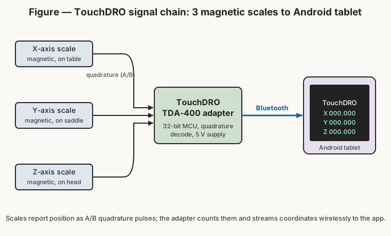
TouchDRO is an open, Android-based digital readout project created by Yuriy Krushelnytskiy (of Yuriy’s Toys). Instead of a fixed glass display welded to a proprietary console, TouchDRO splits the system into three cooperating parts:
- Linear scales on each axis, which measure position and output an electrical signal proportional to movement.
- A small adapter board, which reads the scales, counts their signals into absolute coordinates, and transmits those coordinates wirelessly.
- The TouchDRO Android app running on an ordinary tablet, which receives the coordinates over Bluetooth and presents them on a large multi-touch display — with all the DRO functions (datums, bolt circles, incremental/absolute, unit switching, tool tables) implemented in software.
The appeal of this architecture is threefold. It is inexpensive, because the expensive part of a commercial DRO — the display and its firmware — is replaced by a tablet you may already own and a free app. It is flexible, because the app is updated over time and the same adapter can serve a mill or a lathe. And the display is enormous and legible compared with the cramped LED windows of a budget commercial unit — a full tablet screen showing big digits, at a comfortable viewing angle, is genuinely easier to read across a shop. The TouchDRO app is available free on the Google Play Store; the adapters are sold as kits or assembled boards, or can be built from Yuriy’s published designs.
3.3 Choosing the scales: magnetic vs glass vs capacitive
The scales are where a mill DRO succeeds or fails, and the choice of scale technology is the most consequential engineering decision in the whole build. Three types are common in the hobby world.
Glass (optical) scales are the traditional high-accuracy choice. A read head shines light through (or reflects it off) a precisely etched glass grating and counts the fringes as it moves. They are accurate and available in 5- or 1-micron resolutions, but on a mill they have a real weakness: the optical path is intolerant of contamination. Fine metal chips, cutting-fluid mist, and the sheer mess of milling can foul the grating or the read head if the scale is not well sealed and guarded, and a chip lodged in the wrong place can cause miscounts. Glass scales are also relatively bulky and fragile.
Capacitive scales are the cheapest — they are the same technology as a digital caliper, sensing position by the changing capacitance between a patterned scale and a moving pickup. They are compact and low-cost, but they are the least robust electrically: they are sensitive to electrical noise, to moisture, and to poor grounding, and the very cheapest are prone to erratic readings in a real shop environment. They can work, but they are the fussiest to make reliable.
Magnetic scales are the choice for this machine, and for good reason. A magnetic scale consists of a strip magnetised with alternating north/south poles at a fixed pitch, sealed in a stainless-steel channel, read by a magnetoresistive (MR) sensor in the read head that rides on a small air gap over the tape. Because nothing optical is involved, magnetic scales are tolerant of chips, coolant, and dirt — the very conditions a mill produces — and they shrug off the contamination that would fog a glass grating. They are compact, robust, available in fine resolutions (commonly 5 micron, some 1 micron), and forgiving of the imperfect mounting that a retrofit onto cast-iron ways inevitably involves. Common hobby-grade magnetic scales (the Ditron/AccuRemote family and similar) output a standard A/B quadrature signal that the TouchDRO adapter reads directly. For a mini mill that will spend its life throwing steel and aluminium chips, magnetic scales are the pragmatic, durable answer, and that is what this shop fitted to all three axes.
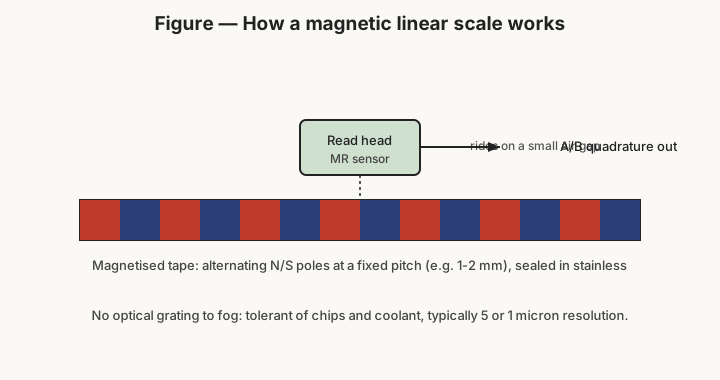
A word on what “quadrature” means, since the whole chain depends on it. A quadrature scale outputs two square-wave channels, A and B, ninety degrees out of phase. Counting the edges gives fine resolution (four counts per signal cycle), and comparing which channel leads tells the adapter the direction of travel. That is how a simple stream of pulses becomes a signed, high-resolution position — and it is why the adapter, not the scale, is where the actual counting and coordinate-keeping happen.
3.4 The TDA-400 adapter
The TouchDRO TDA-400 is the adapter at the centre of this build. It is one of TouchDRO’s current-generation scale-interface adapters, built around a 32-bit dual-core microcontroller, and its job is to read the scales, maintain the axis coordinates, and stream them to the tablet.
Its relevant characteristics for this install:
- Four scale inputs. The TDA-400 handles up to four axes of 5 V quadrature scales — either RS-422 differential or single-ended TTL signalling. The 3990 uses three of those inputs (X, Y, Z); the fourth is spare, available for a future fourth axis or a rotary encoder.
- Broad scale compatibility. It reads modern magnetic, glass, and inductive quadrature scales, which is exactly why the choice of magnetic scales above is a drop-in: the adapter does not care about the sensing technology, only that the signal is 5 V quadrature.
- Bluetooth connectivity to the tablet, so there is no wired run from the adapter to the display — the tablet can be positioned anywhere convenient near the head. (The current adapters also expose a USB link that can be used at the same time as Bluetooth, useful for a computer or for firmware work.)
- 5 V power, with non-volatile memory and power-loss handling so that configuration survives being switched off.
In use, each scale’s read head cable runs to the adapter; the adapter is powered from a small 5 V supply; and the adapter pairs once with the tablet over Bluetooth. From then on, switching the machine on and opening the app brings the readout to life with its scales already configured. The adapter is the quiet workhorse of the system — no display, no controls, just a sealed box that turns three streams of quadrature pulses into three live coordinates.
3.5 Mounting the scales on X, Y, and Z
Fitting the scales is the bulk of the physical work, and the principle is the same on every axis: the scale body is fixed to one member of the moving pair and the read head to the other, so that relative movement between them is exactly the axis travel. Everything else is a matter of protecting the scale, keeping it straight, and finding room for it on a small machine.
X axis (the table). The X scale mounts along the front face of the table, with the scale body running the length of the table and the read head fixed to the saddle or a bracket on the base casting. As the table traverses left–right, the read head moves along the scale, reading true X position. The front of the table is the natural home because it is accessible and roughly the right length, but it is also directly in the chip stream, which is one more argument for the chip-tolerant magnetic scale and for a light guard or shield over it.
Y axis (the saddle). The Y scale is the tightest fit on any mini mill, because the saddle’s in-and-out travel is short (130 mm here) and there is little clear real estate. It typically mounts between the saddle and the base, low and toward the front or side, with brackets fabricated to bridge the gap. It reads the saddle’s fore–aft motion.
Z axis (the head). The Z scale runs vertically along the column, with the scale body on the fixed column and the read head on the moving head casting (or vice versa). It reads the head’s up-and-down travel on the column — note that this measures head motion, not quill motion, which is the more useful of the two Z references for setting working height. Some builders instead scale the quill; measuring the head on the column is the more common and generally more useful choice.
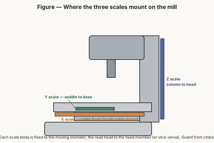
Three practical rules govern every scale mount. First, the scale must be straight and parallel to the axis of travel within the read head’s tolerance — a scale mounted with a bow or a twist will bind or read short, so the mounting surface is checked or shimmed flat. Second, the read head’s air gap must be correct and constant along the whole travel; magnetic scales are forgiving here, but a gap that closes up at one end will still cause trouble. Third, cables must be routed and strain-relieved so that the moving head or table cannot pull, pinch, or chafe them over thousands of cycles — a snagged scale cable is the most common cause of a DRO that “works and then doesn’t.” On a small machine, finding bracketry that satisfies all three without fouling the travels or the handwheels is most of the install effort, and it is why a mini-mill DRO retrofit is a fabrication project as much as an electrical one.
3.6 The tablet and the app
The display side is the easiest part of the system. An ordinary Android tablet runs the free TouchDRO app, pairs once with the TDA-400 over Bluetooth, and is configured with each axis’s scale resolution and direction so that the on-screen numbers count the right way and read true. The tablet is then mounted on an arm or bracket beside the head, at a comfortable height and angle, where its large digits are readable from the working position.
From there the app is the DRO’s brain: it holds the datums, switches inch/millimetre, does the bolt-circle and hole-pattern math, keeps absolute and incremental coordinates, and stores tool offsets — all on a screen far larger and clearer than any budget commercial console. Because it is software on a general-purpose tablet, it also updates and improves over time, and the tablet can be unclipped and taken to the bench or swapped without touching the machine.
3.7 Owner’s build — parts and photos to come
The engineering above is general to a TouchDRO magnetic-scale retrofit on a HiTorque mini mill. This shop’s specific build — the exact scale brand and the length of scale fitted to each axis, the bracketry fabricated for the tight Y and Z mounts, the model and mounting of the tablet, and the routing of the cabling — is documented with the machine’s own hardware, and those particulars and photographs are still being gathered. They will be added here rather than guessed at.
What is fixed, and what makes this machine what it is, is the design: magnetic linear scales on all three axes, a TouchDRO TDA-400 adapter counting their quadrature, and the TouchDRO app on a tablet — an open, chip-tolerant, large-display readout that turns a capable manual mini mill into a genuinely precise one. Volume 4 turns to using it, and to how having that readout changes the way every operation on the machine is set up and run.
Comments (0)