HiTorque 7×16 Mini Lathe · Volume 4
Using It & Tuning — Operations, Fettling, and Safe Practice
4.1 From spinning spindle to finished part
A lathe rewards understanding more than any other machine in the shop, because the operator is directly in the control loop: two hand-wheels, a dial or a DRO, and a sense of what the tool is doing. This volume covers the core operations — turning, facing, parting, drilling, boring, and thread cutting — and then the equally important second half of owning a mini lathe: fettling, the community’s word for the tuning and adjustment that turns a machine as-shipped into one that cuts accurately. It closes with lubrication and safe practice. The techniques here are standard mini-lathe practice, well documented across the hobby-machinist community; the machine-specific numbers are LittleMachineShop’s for the 7450.
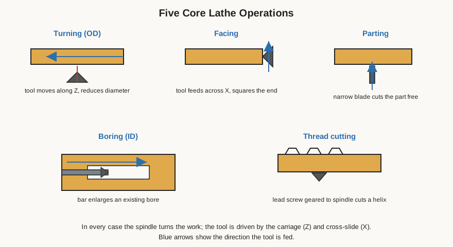
4.2 Turning and facing
Turning is the defining operation: the tool is fed along the work (in Z) at a set depth of cut to reduce its diameter over a length. The operator sets the depth with the cross-slide dial or DRO, engages either a hand feed or the power feed, and lets the tool travel down the work. The keys to a good result are appropriate spindle speed for the material and diameter (higher for aluminum and small diameters, lower for steel and large diameters — the brushless drive’s low-end torque is what makes the low speeds usable), a sharp tool set exactly on center, and — for finish — a fine power feed rather than hand-feeding, which produces a far more even surface. Material is removed in successive passes; a bench lathe takes light cuts and more of them rather than one heavy hog.
Facing feeds the tool across the end of the work (in X) to produce a flat, square face perpendicular to the axis. It is how the end of a part is trued and brought to length, and it is usually the first thing done to a piece of raw stock. Because the tool passes through the center of the work, tool height is critical: a tool even slightly high or low leaves a small uncut pip at the very center. Facing to a length is done by touching off and then advancing the carriage a known amount on the dial, DRO, or a carriage stop.
4.3 Parting and drilling
Parting (cutting off) uses a thin blade fed straight into the work until it severs the finished part from the bar. It is the operation most sensitive to setup on a small lathe: the blade is narrow and buried in its own slot, chips are hard to clear, and any looseness in the carriage or error in tool height invites the dreaded dig-in. Success comes from a rigid quick-change post, the tool dead on center, a slower speed, steady feed, and cutting fluid to clear chips. The 7×16’s low-end torque helps here too, since parting wants force at low RPM.
Drilling on the lathe is done from the tailstock: the work spins, a center drill starts an accurate hole on the axis, and progressively larger drills (in a Morse-taper drill chuck in the quill) open it up as the operator winds the quill forward. Because the hole is bored on the same axis the part is turned on, it comes out concentric — something impossible to guarantee drilling a spinning-tool hole into a part held any other way. Peck the drill to clear chips, and use fluid, especially in steel.
4.4 Boring
Boring enlarges and finishes an existing hole to a precise internal diameter using a boring bar reaching in from the tool post and cutting outward. It is the only way to make a hole that is both an accurate, non-standard diameter and concentric with the part’s other turned features — a bearing seat, for instance. The bar is inherently less rigid than an external tool because it overhangs into the bore, so boring is done in lighter cuts with attention to chatter, but for accurate internal diameters there is no substitute. Depth is controlled with the carriage; diameter with the cross-slide, working outward from a drilled starting hole.
4.5 Thread cutting
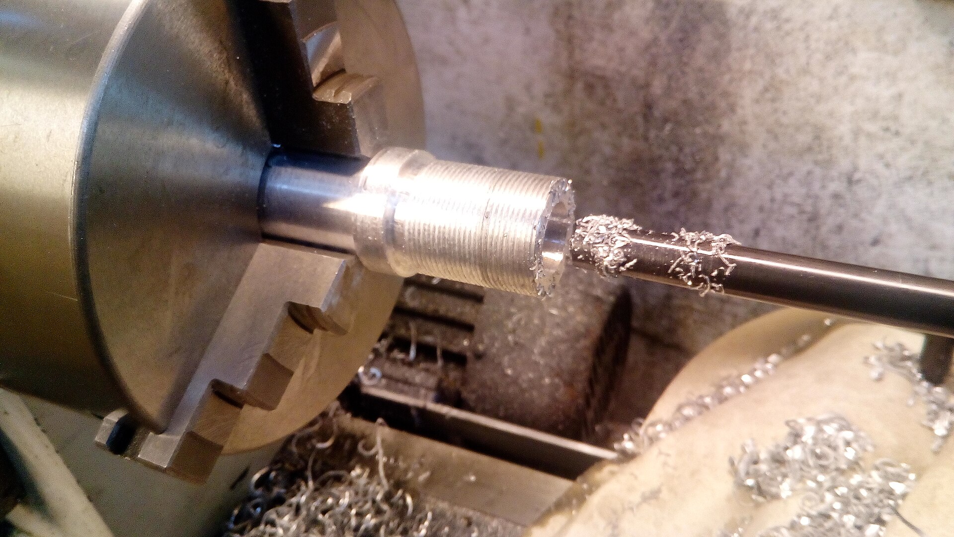
Single-point thread cutting is where a screw-cutting lathe earns its name, and it is the operation that most rewards understanding the machine. The principle is simple: drive the carriage along the work in a fixed ratio to spindle rotation, so a pointed threading tool traces a helix of the desired pitch, and repeat that same helix in progressively deeper passes until the thread is fully formed.
The ratio is set by the change gears. To cut a given thread the operator consults the machine’s threading chart and arranges the correct gears from the supplied 11-gear set in the change-gear train between spindle and lead screw; the reversible 16-TPI lead screw then drives the carriage at the pitch that gearing dictates. The 7×16 is rated to cut 4–80 TPI imperial and 0.3–8.0 mm metric, the metric pitches enabled by the included 21-tooth gear.
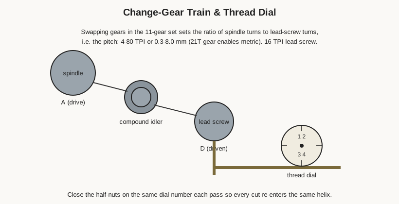
With the gearing set, the mechanics of cutting are these. The compound rest is usually swiveled to about 29–30 degrees so that successive infeeds load mainly one flank of the tool. The tool is set on center and square to the work (checked with a thread gauge). The operator takes a first light scratch pass, then, for each subsequent pass, advances the compound a few thousandths, closes the half-nuts to engage the lead screw at the right moment, runs the pass to the end, retracts the cross-slide, opens the half-nuts, and winds back to the start. On an imperial thread cut on an imperial lead screw the operator can open the half-nuts between passes and re-engage on the thread dial — a small dial geared to the lead screw whose markings show when the half-nuts can be closed so the tool re-enters the existing groove. (For metric threads on this imperial lead screw the half-nuts are generally kept closed and the spindle reversed to return, because the thread dial does not repeat cleanly; this is standard practice and the reason the community pays attention to which threads a given machine “dials.”) The whole procedure is deliberate and slow the first few times and second nature after that, and the machine’s low-speed torque makes the low RPM that threading demands entirely practical.
4.6 Speeds, feeds, and cutting fluid
Underlying every operation are three choices the operator makes and re-makes: how fast to spin the work, how fast to feed the tool, and whether to flood the cut with fluid. Cutting speed — the surface speed at which the tool meets the work — is a property of the material, not the machine, and is what the operator is really setting when dialing in RPM. Aluminum, brass, and plastics tolerate high surface speeds and so spin fast; steels want lower speeds; and because surface speed depends on diameter, a large-diameter part must turn slower than a small one to keep the tool happy. The practical upshot is that the operator drops the RPM as the diameter grows or the material toughens, and the brushless drive’s willingness to hold torque at those low speeds is exactly what makes heavy or large-diameter work in steel feasible on a machine this size.
Feed — how far the tool advances per spindle revolution — trades finish against time: a coarse feed removes metal fast but leaves a visibly ridged surface, while a fine feed leaves a smooth finish slowly. The lead-screw power feed gives a far more even surface than any hand-feed, so finishing passes are almost always taken under power. Depth of cut on a bench lathe is kept modest; material is removed in several light passes rather than one heavy one, both to spare the machine’s rigidity and to leave a clean finishing allowance for a final light pass. Cutting fluid — a soluble oil, cutting oil, or in aluminum sometimes a wax or even WD-40 — cools the edge, lubricates the cut, and flushes chips; it makes the biggest difference in steel and in operations like parting, threading, and drilling where chips are trapped and heat builds. Wiped up after use, it also protects the machined surface from rust. None of these three is a fixed number to memorize; they are a set of relationships the operator learns to read from the color of the chip, the sound of the cut, and the finish left behind.
4.7 Fettling: getting the machine to cut true
A new mini lathe, this one included, is a good machine shipped in a state that assumes the owner will tune it. The hobby-machinist community calls this fettling, and the standard tasks are worth knowing because they are the difference between a lathe that cuts a taper and one that cuts a cylinder.
Adjusting the gibs. The cross-slide and compound ride in dovetail ways, and the fit between the moving slide and its base is set by a gib — a tapered strip pulled in by screws. Too loose and the slide rocks, causing chatter and inaccuracy; too tight and it binds and wears. The gib screws are adjusted so the slide moves smoothly along its whole travel with no perceptible play — snug up until drag just appears, then back off to the point where it disappears, and lock. The saddle gib is set the same way. This is the single most impactful adjustment on the machine.
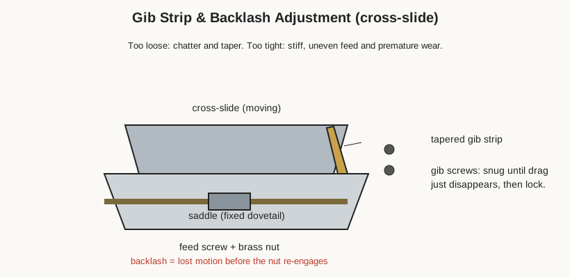
Dealing with backlash. Backlash is the lost motion in the feed screws — the amount a hand-wheel turns before the slide actually moves, caused by clearance between screw and nut. It cannot be eliminated on a machine like this, but it can be minimized by adjusting the nut, and, more importantly, it is managed by always approaching a dimension from the same direction so the slack is taken up consistently. The Deluxe machine’s DRO helps enormously here, since it reads true slide position regardless of backlash in the screw.
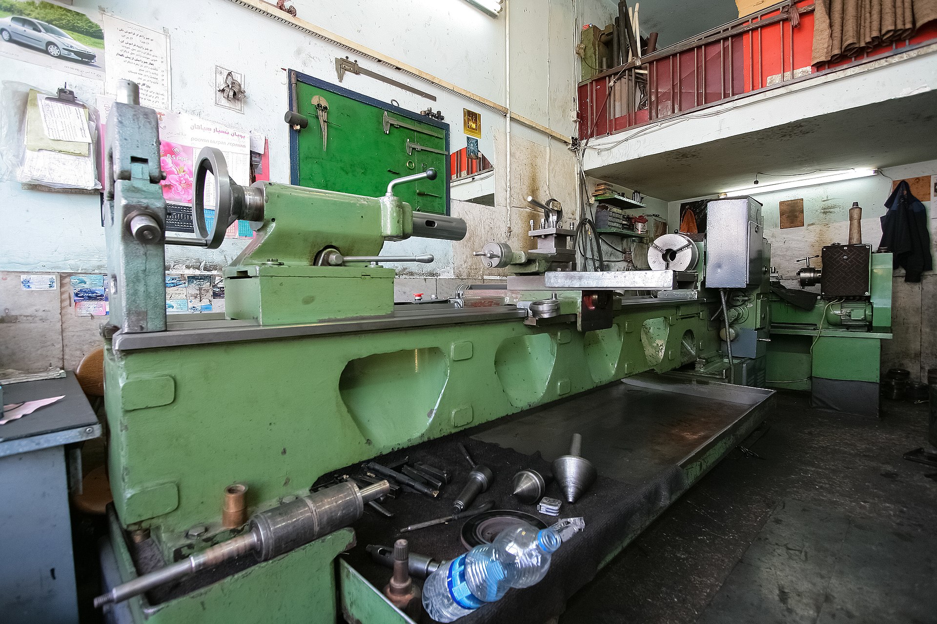
Aligning the tailstock. For turning parallel (not tapered) work between centers, and for drilling straight, the tailstock must be exactly on the spindle axis. It is adjustable side to side, and it is set by turning a test bar between centers and adjusting until the bar comes out the same diameter at both ends (or by indicating the quill), then confirming. A tailstock off to one side turns a taper and drills crooked — a common cause of mysterious inaccuracy on an otherwise good machine.
Leveling — really, de-twisting. A lathe bed sitting on an uneven bench is twisted, and a twisted bed cuts a taper no matter how well everything else is set. “Leveling” the lathe is not about gravity but about removing that twist: the bed is shimmed and the machine adjusted (classically checked with a precision level or, more directly, by the two-collar test — turning two collars a distance apart and comparing their diameters) until the bed is free of twist and the machine turns parallel. On a bench machine this means mounting it to a stiff, flat surface and taking the twist out.
4.8 Lubrication and care
The machine wants routine lubrication to stay accurate and to last. The ways and the exposed slides get a light machine oil (way oil) wiped on before use and the swarf brushed off after; the lead screw and feed screws get oil at their oilers or bearing points; the cross-slide and compound feed screws benefit from a drop of oil in their nuts. Chips should never be allowed to accumulate on the ways or be dragged along them, and cutting fluid used in a cut should be wiped up rather than left to sit. The spindle bearings are sealed and need no routine attention. Periodically the gibs and backlash are re-checked, since they drift as the machine wears in. None of this is onerous — a few minutes before and after a session — but it is what keeps a small lathe cutting like a good one.
4.9 Safe practice
Two finishing steps deserve mention because they are where a part is either completed or quietly ruined. Deburring removes the sharp wire edge and burr left at every cut edge, bore, and parted face — done with a file, a deburring tool, a countersink, or a scrap of abrasive, always with the same care about not touching a spinning chuck. A part that measures perfectly but is left with a razor burr is not finished and is a hazard to handle. Polishing to improve surface finish is sometimes done by holding fine abrasive cloth to the turning work, but it must be done thoughtfully: cloth held by hand near a rotating chuck is a real snag hazard, so it is kept to a backing stick or a strip held taut and well clear of the jaws, never wrapped around a finger.
A lathe is not a fast machine, but its spinning chuck and continuous cutting make it an unforgiving one, and the safety rules are few and absolute. The first and most important: remove the chuck key the instant it leaves the chuck, every time — a key left in a chuck that is then started becomes a projectile. Never wear gloves, loose sleeves, jewelry, or untied long hair near a running spindle; anything that can be caught by the work or chuck will be, and the machine will not stop for it. Wear eye protection against flying chips. Stop the spindle before measuring, adjusting, or changing tooling — never reach over or near a spinning chuck. Take light cuts appropriate to a bench machine rather than forcing it. Keep the work properly and fully gripped in the chuck and support long pieces with the tailstock. Know where the emergency stop is — on this machine it is on the illuminated front panel — before starting, and keep the area around the machine clear of clutter and the floor clear of oil. The mini lathe’s small size can tempt a casual attitude; the spinning chuck and the continuous cut deserve the same respect as any larger machine.
Comments (0)