CNC Coil Winder 1 · Volume 2
Inside the Machine: Spindle, Traverse, Tensioner, and Controller
2.1 The Spindle: the Shaft That Turns and Counts
The heart of any coil winder is the spindle — the powered, horizontal shaft that carries the coil and rotates it. On this machine it projects from the front-right of the drive cabinet as a stout silver shaft, and everything the winder does is measured against its rotation. A motor inside the cabinet turns the spindle; a saved program tells the controller how many times to turn it and how fast; and a sensor on the spindle lets the controller count every revolution. That count is the coil’s turn count. Get the spindle right and the whole machine follows.
Two things about the spindle matter to the maker: how the coil is mounted on it, and how hard and fast it can be driven. Mounting is handled by an arbor or chuck at the end of the shaft — a fixture that grips whatever the coil is being wound on. Bobbins, plastic formers, ferrite pot-core halves, and toroids-on-a-fixture are all held by some form of arbor, usually an expanding or clamping mandrel that the bobbin slides onto and locks against so it turns with the shaft and does not slip. Because the range of things a maker might wind is wide, arbors are the most-swapped part of the machine; a shop typically accumulates a small set of them, plus shop-made adapters turned on the lathe for odd formers. The exact arbor set and thread that came with this unit is a bench detail, noted as an owner’s slot below.
Drive is the spindle’s other headline. This class of machine uses a powerful motor — resellers quote several hundred watts for the M100 size — geared or belted to the spindle so it can spin a loaded bobbin at up to a few thousand revolutions per minute while holding that speed steadily against the drag of the wire and tensioner. Two features make that power usable rather than dangerous. The first is ramping: the controller does not slam the spindle from rest to full speed, but accelerates through a programmed start-slow phase and decelerates through an end-slow phase, so a fine wire is not snapped by a sudden jerk and the last few turns land accurately instead of overshooting. The second is a brake: when the target count is reached the controller actively stops the spindle rather than letting it coast, so the coil ends on the turn the operator asked for. Both behaviours are set as numbers in the program and are covered under the controller below.
2.2 The Traverse: Laying Each Turn Where It Belongs
If the spindle spins the coil, the traverse decides where along the coil each turn lands. It is the feature that separates a CNC winder from a plain motorised one. The traverse is a carriage that carries the wire guide — usually a small pulley or ceramic eyelet the wire threads through — and moves it back and forth parallel to the spindle axis. It rides on a leadscrew driven by its own stepper motor (a motor that rotates in precise, counted steps rather than spinning freely), and the controller drives that stepper in exact proportion to the spindle’s rotation.
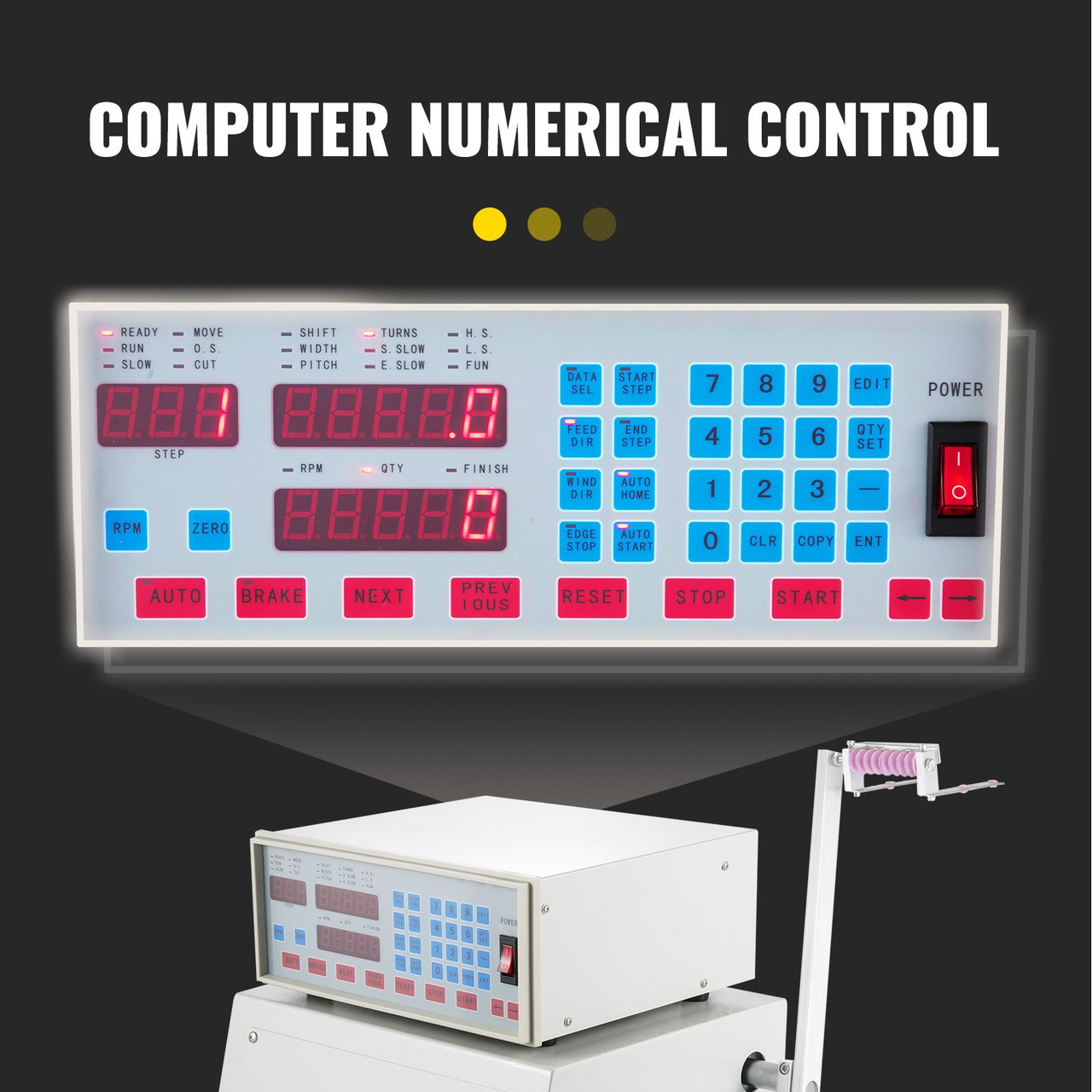
The relationship between the two motions is the concept a maker must hold onto, because it is what every traverse setting adjusts. For each full turn of the spindle, the guide advances along the axis by a set distance called the pitch. Set the pitch equal to the wire’s outside diameter and each new turn falls tight against its neighbour — a close-wound layer, the densest and most common winding. Set the pitch a little larger and the turns are spaced with an air gap between them, which lowers the coil’s self-capacitance and is sometimes wanted in radio-frequency work. When the guide reaches the far end of the winding it reverses and starts a second layer back over the first, and so on until the turn count is met.
From that single relationship comes all the traverse arithmetic, shown in Figure 2. The winding width is the distance between the bobbin flanges — the axial space the wind is allowed to fill. Divide that width by the pitch and the result is the number of turns that fit in one layer. Multiply by the number of layers and the total is the coil’s turn count. The controller works this the other way round for the operator: enter the width, the pitch, and the total turns, and it figures out how many layers the wind will take and where to reverse the guide. The two travel limits — where the guide starts and where it turns around — are set as the start point and end point (or width) in the program. On this class of controller the traverse speed itself is selectable across a range of steps, so a delicate fine-wire wind can crawl while a heavy single-layer coil can be laid quickly.
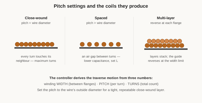
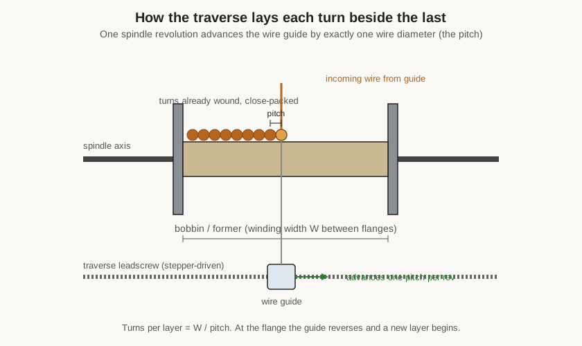
Figure 3 shows why the traverse is worth the extra motor. On a manual winder the operator’s fingers do this job, guiding the wire back and forth by feel; the results are only as even as the operator is patient, and a high-turn multi-layer coil is genuinely hard to keep tidy by hand. The CNC traverse does it identically for hour after hour, which is what makes neat, high-count, multi-layer coils practical on the bench. The finer points of technique — when to close-wind, when to space, how to handle the turn-around at the flange on a very fine wire — belong to the winding-practice material in the “Coils and coil winding” reference dive; here the point is simply that the machine can be told to do any of them with three numbers.
2.3 The Controller: Where the Recipe Lives
The controller is the box on top, and it is the reason the machine deserves the letters “CNC.” It is a dedicated microcomputer with a sealed membrane keypad and a bank of red seven-segment LED displays, and it holds the winding recipe, drives the spindle and traverse motors to it, counts the turns, and stops on target.
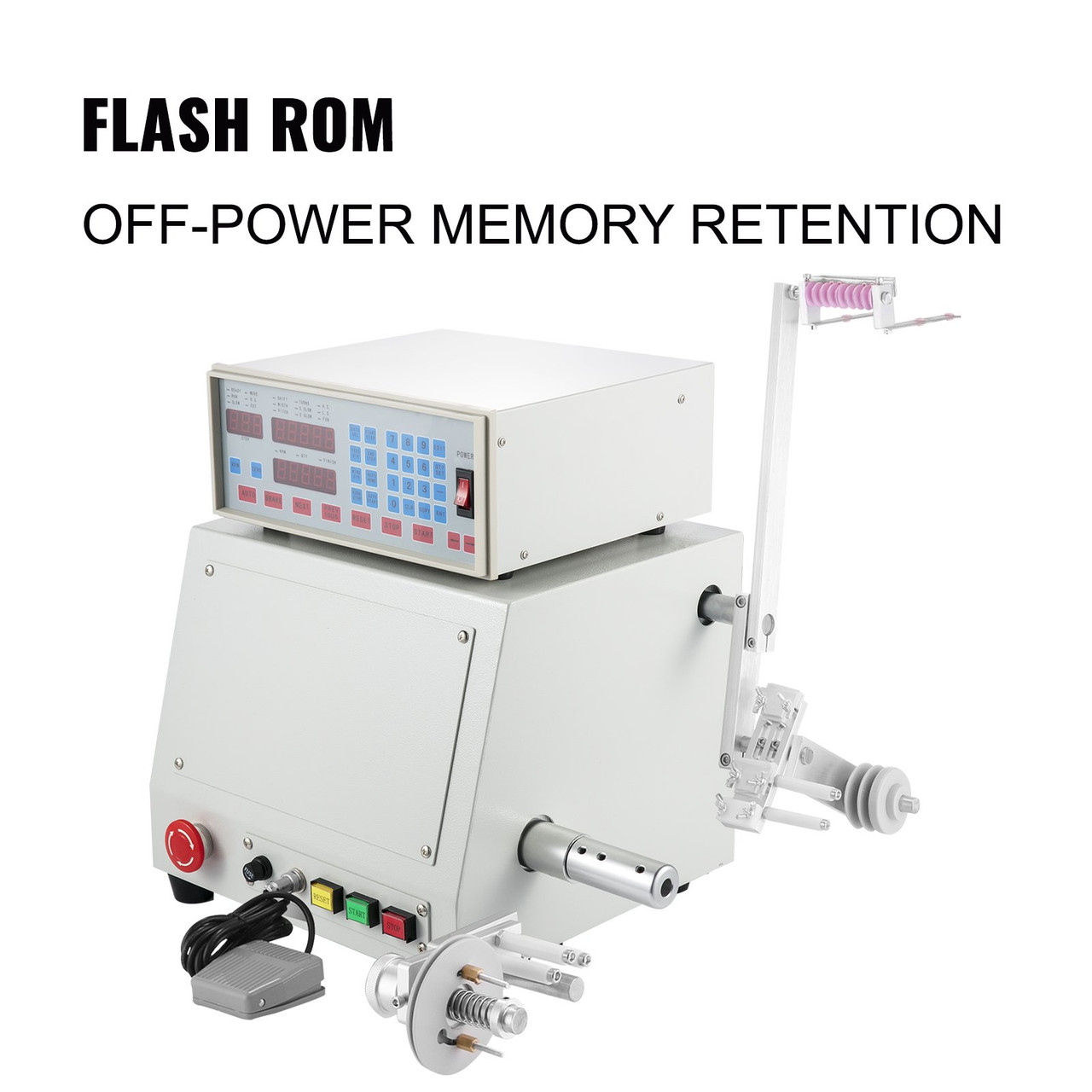
Figure 4 rewards a slow look, because every job in Volume 3 is done from this panel. The displays report the machine’s state: one shows the current program step, another the live turn count as the coil winds, another the RPM, quantity, and a “finish” flag. The counter resolves to a tenth of a turn — fine enough that a fractional-turn tap or a precise end position can be dialled in. The indicator LEDs across the top name whatever the operator is currently editing or watching: WIDTH, PITCH, TURNS, the shift/offset, and the speed states (start-slow, end-slow, high-speed, low-speed), plus the run-state lamps READY, RUN, and SLOW. The blue keys enter and select: a numeric pad for typing values, DATA SEL to pick which stored program is active, START STEP and END STEP to bound a winding step, FEED DIR and WIND DIR to set the traverse and spindle directions, AUTO HOME to return the guide to its start, EDGE STOP for behaviour at the flange, AUTO START, plus EDIT, QTY SET, CLR (clear), COPY, and ENT (enter). The red keys are the action buttons — AUTO to run the stored program, BRAKE, NEXT and PREVIOUS to step through a multi-step wind, RESET, STOP, and START — with arrow keys to jog the traverse by hand.
Three controller behaviours are worth calling out because they are what make the machine trustworthy for unattended running. The first is the auto-stop: the operator enters a target turn count, and the controller ramps down and brakes the spindle exactly on it, so the count is enforced by the machine rather than watched by the operator. The second is program memory: a fully dialled-in wind — wire, width, pitch, turns, speeds, directions — is saved under a program number, and this class of controller stores a large library of them (commonly quoted as up to 999) in flash memory that keeps its contents when the machine is switched off. The third is multi-step programming: a single program can chain several winding steps, pausing between them, which is how the machine handles a coil with a tap, or a transformer with a primary and secondaries, or any wind that changes turns partway through. The programming details — which key does what, in order — are laid out as a working procedure in the next volume.
2.4 The Tensioner and Dereeler: Delivering the Wire Evenly
A coil is only as neat as the wire feeding it, and two subsystems on the delivery arm control that: the dereeler and the tensioner. The dereeler is the spool holder that carries the supply reel of magnet wire and lets it pay out smoothly as the machine pulls wire off. The important word is smoothly: a spool that jerks, over-runs when the machine decelerates, or binds and snatches will spoil the wind or snap a fine wire. Dereelers therefore include some drag of their own — a friction brake on the spool — so the reel is always under slight restraint and never free-wheels ahead of demand.
The tensioner sits between the dereeler and the guide and sets the working tension in the wire as it lands on the coil. In its commonest form it is a pair of felt-faced discs or a small pulley train that the wire threads between, with a spring pressing the faces together; tightening the spring raises the friction and so the tension. Correct tension is a Goldilocks setting and a genuinely important one. Too little, and the turns are loose, the coil is soft and oversized, and turns can slip out of place. Too much, and a fine enamelled wire stretches, thins, or breaks, and the enamel insulation can be scraped through against the guide. The right tension holds each turn firmly against the form and its neighbours without deforming the wire, and it must stay consistent from the first turn to the last so the coil is uniform. Because the ideal setting depends on the wire gauge, tensioning is one of the settings a maker adjusts for every job; the feel for it, and the failure modes, are covered in the winding-practice sections of the “Coils and coil winding” reference dive. The specific tensioner fitted to this unit, and any spare guide eyelets or inserts supplied with it, are bench details noted as an owner’s slot.
2.5 Wire Range, Capacity, and Power
Two numbers bound what the machine can wind: the wire it will handle and the coil it will fit. For this class of winder the wire range runs from very fine enamelled copper — around 0.03 mm, roughly AWG 48 — up to a little over a millimetre, about 1.2 mm or AWG 16. That span covers almost everything a hobby electronics shop winds, from the thousands of turns of hair-fine wire in a high-impedance or ignition coil to the heavier single-layer windings of a power inductor. The coil capacity is set by the winding width and the maximum bobbin diameter, both around 100 mm on the M100-size machine — the source of the name — which comfortably accommodates small mains and switch-mode transformers, filter chokes, and most inductors a maker would build by hand. A worked wire-gauge chart appears in the reference volume.
Power and the operator controls round out the machine. It runs from a single-phase mains supply — units are sold in both 110 V and 220 V forms — and the drive cabinet houses the spindle motor, the stepper driver for the traverse, the DC speed-control and brake circuits, the power supply, and a cooling fan to keep the drive electronics from overheating during long runs. On the front are the safety and convenience controls a production tool needs: a mushroom emergency-stop button that cuts the drive at a slap, a foot pedal that leaves both hands free to guide and manage the wire while starting and stopping the spindle, and RESET, START, and STOP buttons duplicated from the keypad. The exact motor rating, mains voltage, and any options fitted to this particular used purchase are confirmed from the machine itself and are recorded as owner’s slots. With the parts all named, the next volume puts them to work: setting up and running a real wind from bare bobbin to finished, verified coil.
Comments (0)