CNC Coil Winder 1 · Volume 3
Using It: Setting Up, Winding, Tapping, and Verifying a Coil
3.1 From Numbers on Paper to a Part on the Bench
By the time a coil reaches the winder, the hard design decisions are already made: the core or former is chosen, the wire gauge is picked, and the turn count for the target inductance or the transformer’s turns ratio is worked out. All of that lives in the “Coils and coil winding” and coming “Transformers and transformer winding” reference dives, and this volume assumes it is done. What remains is a physical procedure — mount the form, thread the wire, enter the numbers, run the wind, and check the result — and that procedure is what the CNC winder is built to make quick and repeatable. This volume walks it through end to end, in the order a maker actually does it.
The order matters because a coil-winding session has a natural rhythm: prepare the machine and the wire path first, dial in the program second, run third, and verify last. Skipping ahead — starting a wind before the tension is set, or before the counter is zeroed — is the usual way to waste a bobbin. The machine will do exactly what it is told, promptly and precisely, including the wrong thing.
3.2 Mounting the Bobbin or Former
The first job is to get the coil form onto the spindle so it turns true. Whatever is being wound — a plastic bobbin, a machined former, a pot-core half, or a toroid held in a fixture — it must be gripped by the arbor so that it rotates with the shaft and does not slip, wobble, or creep along the spindle under the sideways push of the wire. For a standard flanged bobbin this usually means sliding it onto an expanding mandrel and locking it, so the bobbin’s centre is on the spindle axis and its flanges run square. A form that runs even slightly off-centre will throw the wire tension in and out on every revolution and produce a lumpy, uneven wind, so a moment spent checking that the form spins true — a slow hand-turn of the spindle, watching a flange edge against a fixed reference — is time well spent before any wire is threaded.
The winding width the machine will use is set by the space between the bobbin’s flanges (or, on an unflanged former, by the start and end points the operator chooses). It is worth measuring that width with calipers rather than trusting a nominal figure, because it goes straight into the traverse arithmetic: the number entered for width, divided by the pitch, is what the controller uses to decide where to reverse the guide. A width entered a millimetre too wide will drive the guide into the flange; a millimetre too narrow will leave a gap and start the next layer early.
3.3 Threading the Wire and Setting Tension
With the form mounted, the wire is run from the supply spool through the delivery path to the coil. The path is fixed in shape — dereeler, then tensioner, then guide, then form — and Figure 1 shows the standard route.
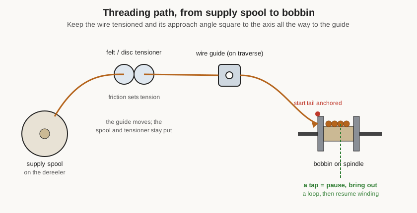
The supply spool goes on the dereeler, whose own light brake keeps it from over-running. The wire is then led through the tensioner — between the felt-faced discs or around the pulleys — and finally through the wire guide on the traverse. Threading through the tensioner is where the working tension is set: the spring pressure on the discs is adjusted so the wire is held firmly but not stretched. As Volume 2 stressed, this is a per-wire setting, tighter for heavy wire and much lighter for fine, and the feel for it — and the failure modes of getting it wrong — is covered in the winding-practice material of the reference dive. A quick sanity check is to pull a length of wire through the threaded path by hand: it should come with a smooth, steady drag, not free-running and not snatching.
With the path threaded, the start tail is anchored to the bobbin. Every coil needs its beginning fixed so the first turns cannot pull loose — commonly by hooking the tail through a hole in the flange, tucking it under the first few turns, or taping it to the form — leaving enough loose wire to make the eventual connection. Only once the tail is anchored and the guide is positioned at the start point is the machine ready to be programmed.
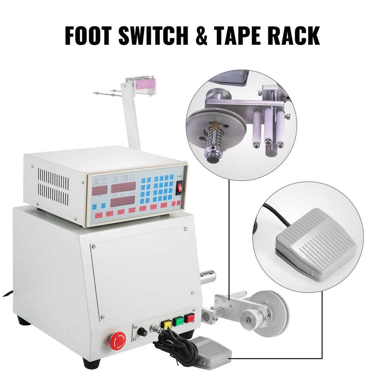
Figure 2 shows two conveniences that matter more in practice than they look. The foot switch lets the operator start and stop the spindle without taking a hand off the wire, which is invaluable when threading the first turns or when nursing a fine wire onto the form. The dereeler clamp holds the supply spool with a spring-loaded friction brake, the source of the light back-drag that keeps the wire under control. Neither is glamorous, but both are the difference between a relaxed setup and a fumbled one.
3.4 Entering the Program
Now the numbers go into the controller. The sequence is the same for a simple inductor and, step by step, for a multi-winding transformer, and Figure 3 lays it out.
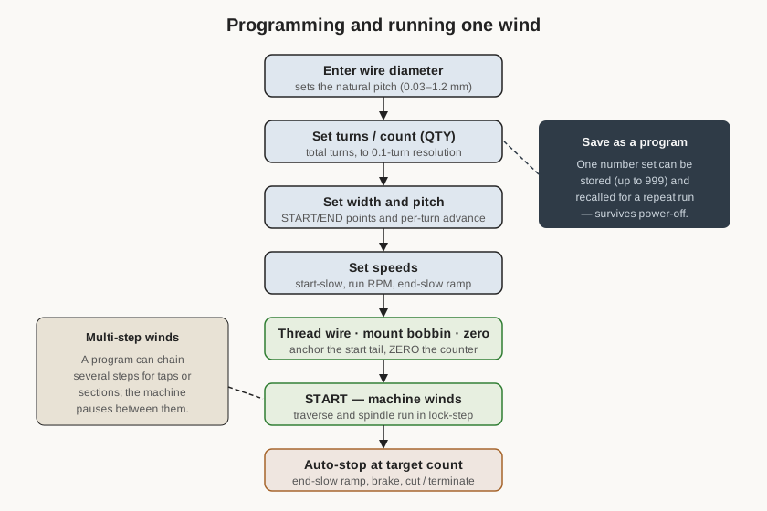
Working down Figure 3: the wire diameter is entered first because it sets the natural pitch for a close wind — one wire diameter of guide advance per spindle revolution. The turn count (the QTY or turns value) is entered next; on this controller it resolves to a tenth of a turn, so a precise end position or a fractional-turn detail can be dialled in. The winding width and pitch are set from the measured bobbin — width between the flanges, pitch equal to the wire’s outside diameter for a close wind or larger for a spaced one — and the controller derives the turns-per-layer and the reverse points from them. Finally the speeds are set: a gentle start-slow ramp so the wire is not jerked at the outset, a run speed for the bulk of the wind, and an end-slow ramp so the last turns land accurately before the brake stops the spindle on the target count.
Two habits make this reliable. The first is to zero the counter immediately before starting, so the displayed count is the actual turns on this coil and not a leftover from the last job. The second is to save the program once it is dialled in and proven, under one of the controller’s many program numbers; the settings are held in flash memory and survive power-off, so the next identical coil is a matter of recalling the program rather than re-entering every value. For a shop that winds matched sets or repeat batches, this is where the machine pays for itself.
3.5 Running the Wind
With the program entered and the counter zeroed, the wind is run — typically by selecting AUTO and pressing START, or via the foot switch. From here the machine takes over: the spindle accelerates through the start-slow ramp, the traverse guide walks the wire back and forth in lock-step laying each turn beside the last, the layers build and reverse at the flanges, and the live count climbs on the display. The operator’s job during the run is not to guide the wire — the traverse does that — but to watch: to confirm the wire is landing cleanly, that the tension looks right, that the spool is paying out smoothly, and that nothing is snagging. A hand near the emergency stop and an eye on the wire is the right posture, especially for the first coil of a new setup before the program is trusted.
As the count approaches the target, the controller enters the end-slow ramp and brakes the spindle exactly on the programmed turn count. The wind stops itself; the operator does not have to catch it. The finish tail is then secured the same way the start was — anchored so the last turns cannot unravel — and the wire is cut, leaving enough length for the connection. For a plain single-winding inductor, that is the whole run: mount, thread, program, wind, secure, cut.
3.6 Transformers, Taps, and Multi-Section Winds
A transformer, or any coil with more than one winding or a tap, is the same procedure repeated in steps, and the controller’s multi-step programming is what makes it manageable. A mains or switch-mode transformer, for instance, is a primary winding and one or more secondaries on the same bobbin, wound in sequence with insulation between them — a wrap of tape or film that both holds the layer down and provides the voltage isolation the design calls for. The machine winds the primary to its turn count and stops; the operator adds the interlayer insulation and brings out the winding’s leads; then the next step winds the secondary to its turn count, and so on. Each step is a saved set of numbers, and NEXT and PREVIOUS on the keypad walk through them. The transformer-specific craft — winding order, insulation, isolation, and turns-ratio verification — is the subject of the coming “Transformers and transformer winding” reference dive; the machine’s role is to lay each winding accurately and to stop on each step’s count.
A tap — a connection brought out partway along a winding — is handled the same way, as shown back in Figure 1. The wind is programmed as two steps: wind to the tap count and stop; bring out a loop of wire (or cut and rejoin, depending on the design) to form the tap connection; then resume and wind to the final count. Because the controller stops precisely on the first step’s count, the tap lands on exactly the turn the design specifies, which is difficult to guarantee by hand on a high-turn coil. Multi-tapped coils are simply more steps in the chain.
3.7 The Setup Mistakes Worth Naming
A CNC winder fails in a small number of predictable ways, nearly all of them setup errors rather than machine faults, and knowing them shortens the learning curve. The commonest is a form that does not run true: a bobbin mounted slightly off-centre or loose on the arbor throws the tension in and out on every revolution and produces a lumpy wind, so the check for concentricity before threading is not optional. The second is wrong tension — too loose gives a soft, oversized coil with turns that wander; too tight stretches or breaks a fine wire and scrapes its enamel — and because tension is a per-wire setting, it is worth re-checking every time the wire gauge changes. The third is a pitch entered from the bare-copper diameter rather than the over-enamel outside diameter, which leaves a close-wound layer slightly loose and slowly walks the turn count out of register across a wide bobbin. The fourth is forgetting to zero the counter, so the coil ends up with the previous job’s residual count added to it. And the fifth is starting a trusted-looking program on a form whose measured width does not match the width in the program, which drives the guide into a flange or reverses it early. None of these is subtle once seen, and all of them are cheaper to catch before the wind than after a bobbin has been spoiled.
3.8 Verifying the Result
A wind is not finished when the machine stops; it is finished when the coil has been checked. The most basic verification is the turn count itself, which on a CNC winder is largely a matter of trusting a well-set-up machine — the counter enforced the number — but it is still worth confirming that the program’s target matched the design and that no step was skipped. Visually, the coil should be inspected for a tidy, even wind with no crossed or pinched turns, no damaged enamel, and secure start and finish tails.
The electrical check is where the coil proves it matches its design, and it is done with test gear rather than the winder. For an inductor, an LCR meter measures the inductance (and, at a chosen frequency, the Q and the DC resistance), which is compared against the target the coil was wound to hit; a value off by more than a little points to a miscount, the wrong core, or a wire problem. For a transformer, the turns ratio is checked by measuring the voltage on each winding when a known AC voltage is applied to another, confirming the ratio the design called for, and the windings are checked for isolation and continuity. These measurement techniques — what to measure, on what instrument, and how to read the result — are covered in the measuring-and-testing material of the “Coils and coil winding” reference dive, which this machine dive defers to rather than duplicating. The division of labour is clean: the winder makes the coil to a number, and the test bench confirms the number was right. Once it checks out, the proven program is saved, and the next identical coil is minutes of work rather than a fresh setup. The final volume gathers the machine’s specifications, its maintenance, and the reference links in one place.
Comments (0)