CNC Coil Winder 1 · Volume 4
Reference: Specifications, Maintenance, and Further Reading
4.1 What the Machine Is, in One Place
This closing volume gathers the machine’s numbers, its upkeep, and its cross-links so they can be found without hunting back through the narrative. It also draws the honest line this series has kept throughout: the class of machine is documented from the manufacturers’ and resellers’ own specifications and is reliable; the specific unit’s exact configuration, being a used eBay purchase, is confirmed only from the machine itself, and those points are marked as owner’s slots to be filled from the bench. Where a figure below is a class-typical value rather than a measured one for this unit, it is described as such.
4.2 Specifications at a Glance
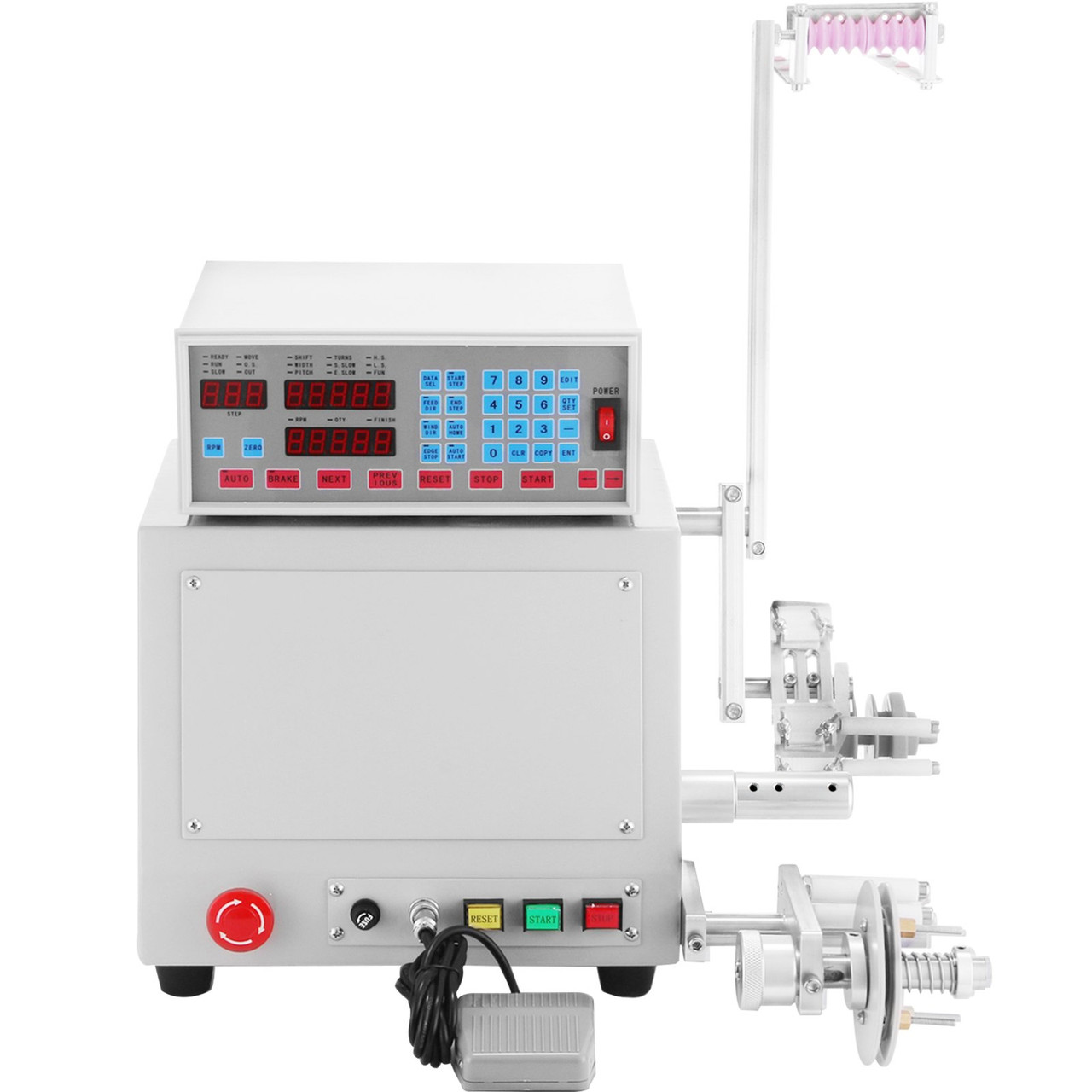
The table below lists the specifications typical of this class of benchtop CNC coil winder (the “M100”-size machine). Treat each as the expected value for this unit pending bench confirmation; the exact figures for the shop’s specific machine are recorded in the owner’s slots that follow.
Table 1 — Specifications at a Glance
| Parameter | Class-typical value | Notes |
|---|---|---|
| Machine type | Benchtop CNC (computer-controlled) coil winder | Stepper/step-servo spindle + stepper-driven traverse |
| Wire diameter range | ≈ 0.03–1.2 mm (≈ AWG 48 to AWG 16) | Enamelled copper magnet wire; see Figure 3 |
| Max winding width | ≈ 100 mm | Between bobbin flanges (source of the “M100” name) |
| Max bobbin / former diameter | ≈ 100 mm | |
| Turn-count resolution | 0.1 turn | Fractional-turn taps and end positions possible |
| Spindle speed | up to a few thousand RPM | With programmed start-slow / end-slow ramps and a brake |
| Traverse drive | Stepper motor + leadscrew | Pitch and width programmable; multi-step selectable speeds |
| Program memory | Up to ~999 winding programs | Non-volatile flash; retained through power-off |
| Controller | Dedicated microcomputer, membrane keypad + LED displays | Turns, width, pitch, speeds, directions, auto-stop |
| Operator controls | Foot pedal, emergency stop, reset/start/stop | Foot pedal frees both hands for the wire |
| Motor power | Several hundred watts (class-typical for M100 size) | Exact rating to be confirmed for this unit |
| Supply | Single-phase mains (110 V or 220 V versions sold) | |
| Cabinet contents | Spindle motor, stepper driver, DC speed/brake circuits, PSU, cooling fan |
A few of these deserve a sentence of context. The wire range is the widest single spec on the machine and the one that defines what it can be used for: from the hair-fine 0.03 mm wire of a high-turn or ignition-type coil up to the 1.2 mm wire of a heavier power inductor, it spans essentially everything a hobby electronics shop winds by hand. The 100 mm width and diameter comfortably take small mains and switch-mode transformers, filter chokes, and most maker-scale inductors. The 0.1-turn resolution and the enforced auto-stop are what make the count trustworthy, and the ~999-program flash memory is what makes repeat and matched-set work fast. None of these is exotic; together they are what separate the machine from a motorised hand-winder.
Owner’s slots to confirm from the bench for this specific machine: exact model designation and badge; motor power rating and whether the spindle drive is a DC motor or a step-servo; mains voltage (110 V or 220 V) as configured; the arbor/chuck set supplied and the spindle thread/bore; the tensioner type and any spare guide eyelets or inserts; the serial number and controller firmware; and the eBay listing particulars (item 326469524310) and as-received condition of the used purchase.
4.3 The Wire Range, Read Off a Scale
Because wire is entered on the keypad in millimetres but often specified in a design by AWG, it helps to see the two side by side across the machine’s range.
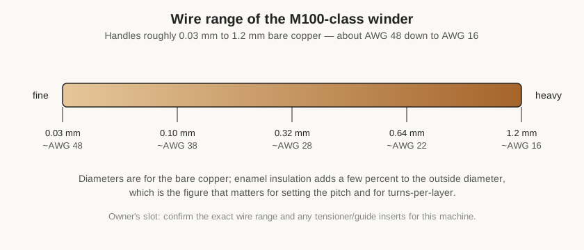
The point Figure 2 makes for setup is the distinction between bare and over-enamel diameter. Design tables and AWG figures usually quote the bare copper, but the wire that actually stacks on the bobbin is the copper plus its insulation, which is a few percent larger. For close-wound layers, entering the outside diameter as the pitch is what makes the turns pack correctly; using the bare figure will leave the layer slightly loose and can throw off the turns-per-layer count over a wide bobbin. A full magnet-wire table — bare and over-enamel diameters, resistance per unit length, and current handling — is maintained in the “Coils and coil winding” reference dive rather than duplicated here.
4.4 Maintenance and Care
A coil winder is a light-duty machine and asks little, but the little it asks is worth doing, because most winding failures trace back to the wire path rather than to the electronics. Maintenance falls into a few plain habits.
Because this machine arrived as a used eBay purchase, its upkeep begins with a commissioning pass before anything else: confirm the mains voltage matches the supply, check that nothing has worked loose in shipping, run the spindle up slowly by hand and then under power to listen for bearing noise or an uneven traverse, and step through the keypad functions to confirm the controller behaves as its legends promise. A used machine may also arrive with worn wire-path parts or a glazed tensioner from a previous owner’s work, so treating the first few winds as calibration runs — proving the count, the pitch, and the tension against a known coil — is the sensible way to establish a baseline the shop can trust. With that baseline set, the routine maintenance below keeps it there.
Keep the wire path clean and smooth. The guide eyelet, the tensioner faces, and any pulleys the wire touches wear a groove over time, and a worn or roughened surface will scrape enamel and shed copper dust. These are the parts to inspect most often; a guide eyelet with a visible groove or a sharp edge should be rotated or replaced before it damages wire. Wipe copper dust and stray enamel flakes off the tensioner and guide between jobs so they do not pack into the felt and change the tension.
Check tension consistency. The felt or disc faces in the tensioner compress and glaze with use, which slowly changes the tension for a given spring setting. If coils start coming out looser or tighter than a proven program used to make them, the tensioner faces are the first suspect; refreshing or replacing the felt restores the feel. The dereeler’s spool brake deserves the same occasional check — it should give a light, steady drag, not seize and not free-run.
Look after the spindle and traverse mechanics. The spindle bearings and the traverse leadscrew are the moving heart of the machine and benefit from being kept clean and lightly lubricated per the maker’s guidance, with grit and copper swarf kept out of the leadscrew threads where they would cause uneven traverse motion. A traverse that hesitates or steps unevenly — visible as an uneven pitch in the finished coil — is often just a leadscrew that needs cleaning.
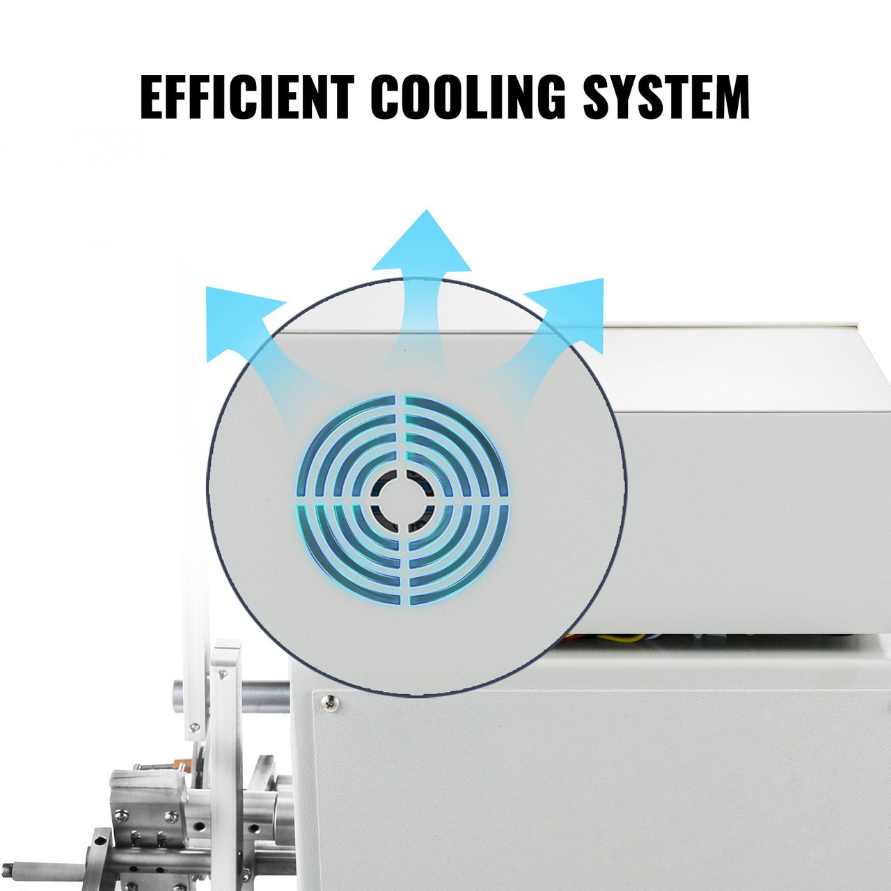
Keep the electronics cool and the connections sound. As Figure 3 shows, the drive cabinet is actively cooled; a fan intake or vent choked with dust lets the drive electronics run hot on long jobs, so keeping them clear is worth the occasional glance. The foot pedal and its cable take repeated flexing and are a common intermittent-fault point on any bench tool, worth checking if the machine starts behaving erratically. And because this is a used purchase, an early pass over the mains lead, the fuse, the emergency-stop function, and the earth connection is simply good practice before the machine is trusted for unattended runs.
Back up the programs conceptually. The controller holds its program library in flash memory that survives power-off, but flash is not immortal and a controller can be replaced. For any program that represents real setup effort — a matched inductor, a multi-step transformer — it is worth writing the numbers down (wire, width, pitch, turns per step, speeds) in a shop notebook or file, so a proven wind can be re-entered if the stored copy is ever lost.
4.5 Safety Notes
The machine is not dangerous in the way a table saw is, but it has a few hazards that reward respect. The spindle spins at speed with the coil, arbor, and any protruding tail on it; loose sleeves, long hair, and dangling cuffs belong well clear, and the wire tail should be trimmed or secured rather than left to flail. The wire itself is a hazard in two directions: fine enamelled wire under tension can snap and whip, and a snapped heavier wire can leave a sharp end, so eye protection is sensible during a run and a hand should never be run along a moving wire to “guide” it. The emergency stop exists precisely for the moment something snags or the wire breaks mid-wind, and its function should be confirmed to work — a slap that actually cuts the drive — before the machine is trusted for a long or unattended run. Finally, because this is a used mains-powered purchase, the earth connection, the mains lead, and the fuse warrant an early inspection; a bench tool that will be left running while the operator manages wire deserves to be electrically sound first.
4.6 Where This Machine Connects
This deep dive is the machine half of a larger story that lives across two sites, and the cross-links are worth restating because they are the intended way to read it.
On the shop side, this winder sits in the Coil Winders group of the Model Shop alongside its two siblings — a second eBay-bought CNC winder and a homemade CNC winder built in-house — each with its own dive. The three together cover the shop’s coil and transformer production, and the reader interested in how a boxed CNC machine compares with a shop-built one will find the contrast drawn out across those dives.
On the reference side, the winding theory and craft deliberately live elsewhere so this machine dive can stay focused on the machine. The “Coils and coil winding” dive (on the Research site, under Electrical Components) is the companion for everything about inductors as components and about the craft of winding them: the physics of inductance, core materials, magnet wire and the AWG tables, winding geometries, turns counting and tension technique, designing a coil for a target inductance, and measuring the finished part on an LCR meter. The coming “Transformers and transformer winding” dive is the companion for transformer-specific work: turns ratios, winding order, interlayer insulation and isolation, and turns-ratio verification. This machine is what turns the designs in those dives into physical parts; those dives are where a reader goes to decide what to wind and why, before coming here to wind it.
Further Reading
For the machine class itself, the most useful public references are the product pages and manuals of the resellers who sell this M100-size winder under their various brands — the specifications, keypad legends, and programming steps they publish match the machine documented here closely enough to fill gaps while the shop’s own unit awaits a full bench write-up. For the winding craft and the electrical background, the two reference dives named above are the primary sources this series leans on, and they in turn cite the magnetics manufacturers’ literature (the ferrite and powdered-iron core makers, the magnet-wire suppliers) for the numbers behind coil and transformer design. The owner’s slots throughout this dive mark exactly where the shop’s specific machine — its badge, its motor, its arbors, and the real coils it has wound — will replace the class-typical account with the particulars of this unit.
Read as a set, the four volumes form a single arc: what the machine is and why the shop keeps it, what each subsystem does, how a wind is set up and run, and — here — the numbers and upkeep to keep it earning its place on the bench. The reference dives supply the theory on either side of that arc, and the shop’s own photographs and measured specifications will, in time, close the remaining slots and turn this class-typical account into a complete record of one specific, well-used machine.
Comments (0)