CNC Coil Winder 2 · Volume 2
CNC Coil Winder 2 — The machine in detail: spindle, traverse, tensioner, controller
2.1 The four subsystems and how they cooperate
Everything a CNC bench winder does resolves into four subsystems working in step: a rotating spindle that carries the bobbin and defines the turn count, a traverse that lays each turn beside the last, a tensioner that holds the wire taut on its way in, and a controller that programs and coordinates the whole thing. The cleverness of the machine is entirely in the coordination — the controller advances the traverse by exactly one wire diameter for every revolution of the spindle, so that a stack of turns comes out even without an operator touching the wire. Understanding the machine means understanding those four parts and the single relationship that links them.
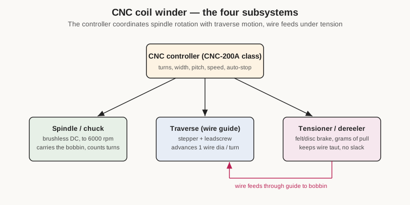
The rest of this volume walks each subsystem in turn, using the specifications and controls of this class of machine (the Minsu-Automation CNC-200A controller and the common 0.03-1.2 mm mechanical platform), and closes on how this unit is set up to complement winder 1 rather than duplicate it. As in Volume 1, the machine’s own plate values are left as owner’s slots where they can only be read off the physical unit.
2.2 The spindle, chuck, and arbor
The spindle is the driven shaft the coil is built on. On this class of machine it is turned by a brushless DC motor — commonly rated 400 W, with 600 W and 750 W “large torque” versions offered for heavier wire and larger formers — through a belt or direct coupling, and it is capable of a claimed top speed in the region of 6000 rpm. That headline speed is almost never used for real work; fine wire and large-diameter formers are wound far slower, and the controller’s speed settings exist precisely so the operator can hold the surface speed of the wire within what the tensioner and the wire itself can tolerate. High spindle speed matters mostly for high-turn-count fine-wire coils where thousands of turns at a sane surface speed would otherwise take an unreasonable time.
Critically, the spindle is what the controller counts. An encoder or the motor’s own commutation feedback tells the controller how far the spindle has rotated, and the turn count on the display is a direct read of spindle revolutions, resolved on this controller to 0.1 of a turn. That tenth-turn resolution is what lets the machine stop cleanly at a fractional turn and what makes tapping at a defined point repeatable. The spindle can be commanded to a fixed-point stop, and the controller is designed so that on a restart it zeroes only the integer part of the turn count and preserves the fraction — a detail that matters when a wind is paused for a tap and resumed.
What actually grips the work varies by job. The machine ships with a way to mount a bobbin or former on the spindle — typically a small chuck or a threaded arbor/mandrel with clamping washers or nuts that trap the bobbin’s flanges against a shoulder so it cannot slip or wobble. For non-standard formers the shop makes or buys arbors sized to the bobbin bore. Getting the former running true on the arbor, with its axis concentric to the spindle, is one of the setup steps that most affects winding quality: a bobbin that runs out (wobbles) will vary the wire tension once per revolution and can walk the winding.
2.3 The programmable traverse and pitch
The traverse is the wire guide that moves parallel to the spindle axis, and it is the part that makes the difference between a neat machine-wound coil and a random-wound tangle. On this class of machine the guide rides on a leadscrew driven by its own stepper motor with a constant-current driver, entirely separate from the spindle drive. Because it is a stepper on a leadscrew, its position is known in absolute terms and can be commanded in millimetres.
The controller ties the traverse to the spindle through the PITCH parameter, which on the CNC-200A is literally entered as the diameter of the copper wire (settable to thousandths of a millimetre). For each revolution of the spindle the controller steps the traverse by that pitch value, so consecutive turns land exactly one wire-diameter apart — a close-wound layer with no gaps and no overlaps. Two more parameters bound the motion: SHIFT, the start position of the guide along the axis (settable across the full travel), and WIDTH, the axial region the guide is allowed to sweep. When the guide reaches the edge of the WIDTH window it reverses and begins the next layer, so WIDTH is effectively the winding window of the bobbin between its flanges.
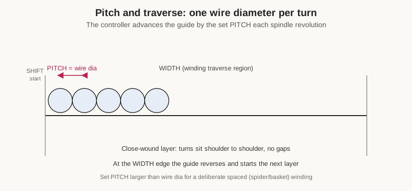
Setting PITCH equal to the wire diameter gives the normal case, a tight single-file layer. Deliberately setting PITCH larger than the wire diameter produces a spaced winding — the turns are laid with air gaps between them, which is how a spaced solenoid, a low-self-capacitance RF coil, or a spider/basket-style winding is made. The controller also lets each programmed step choose a guiding direction (forward or reverse) and whether to suspend at the edges of the width, and offers a modest number of traverse speed steps so the guide’s motion can be slowed for fine wire. Because SHIFT, WIDTH, and the travel limits can be taught by jogging the guide to a position with the panel keys rather than typed as numbers, an operator can set the winding window by eye against the actual bobbin and let the controller remember the coordinates.
2.4 The tensioner and dereeler
Tension is the quiet variable that decides whether a winding is any good. Too little and the turns are loose, the coil is bulky and rings, and the wire wanders off the intended pitch; too much and fine wire stretches (changing its resistance and, past a point, its diameter) or simply snaps. The machine’s job is to hold the incoming wire at a steady, adjustable pull the whole time it is being laid.
On this benchtop class the tensioner is a passive mechanical brake rather than a servo. The common arrangement is a pair of felt or fibre discs squeezed by an adjustable spring, or a small disc-and-spring pulley, that the wire threads between; tightening the spring increases the drag and thus the tension, measured in grams of pull. A supply spool position (dereeler) holds the wire spool so it pays off smoothly without the spool’s own inertia jerking the wire. For the fine end of the range a light, sensitive tensioner is essential — dedicated fine-wire dereelers for 0.04-0.2 mm wire run tensions in the tens to a few hundred grams — while heavier wire in the 0.2-2.0 mm range wants a firmer, graduated tensioner. This is one of the main reasons a shop dedicates a machine to a gauge band: the tensioner is set up and left alone for that band.
Because the tensioner here is passive, the operator — not the machine — is responsible for tension. There is no closed-loop feedback that measures grams and corrects; the felt drag plus the geometry of the wire path is the whole system. In practice that is fine for a bench winder wound at moderate speed, and it keeps the machine simple and robust. It does mean the tension must be checked whenever the wire gauge or spool changes, and that winding speed and tension have to be considered together — running fast increases the dynamic tension the passive brake sees, which is another reason the controller’s speed settings exist.
Volume 3 covers threading and setting tension as a procedure; the point here is architectural: the tensioner is a standing part of the machine’s configuration, and keeping it dressed for a gauge band is exactly what makes a dedicated second winder worthwhile.
2.5 The CNC controller and interface
The controller is the machine’s brain and, on this class, the part that most distinguishes it from a hand-cranked or dumb-motorised winder. The common unit is the Minsu-Automation CNC-200A or a near-equivalent: a single-chip microprocessor design that integrates the stepper-motor driver for the traverse, the DC speed controller and brake for the spindle, and the power supply into one control box. Its front panel carries a keypad, three digital display windows (step number, data, and a counter/RPM window), and a bank of status indicators (READY, RUN, SLOW, MOVE, CUT for wire-break, FINISH, and the RPM/QTY counter mode).
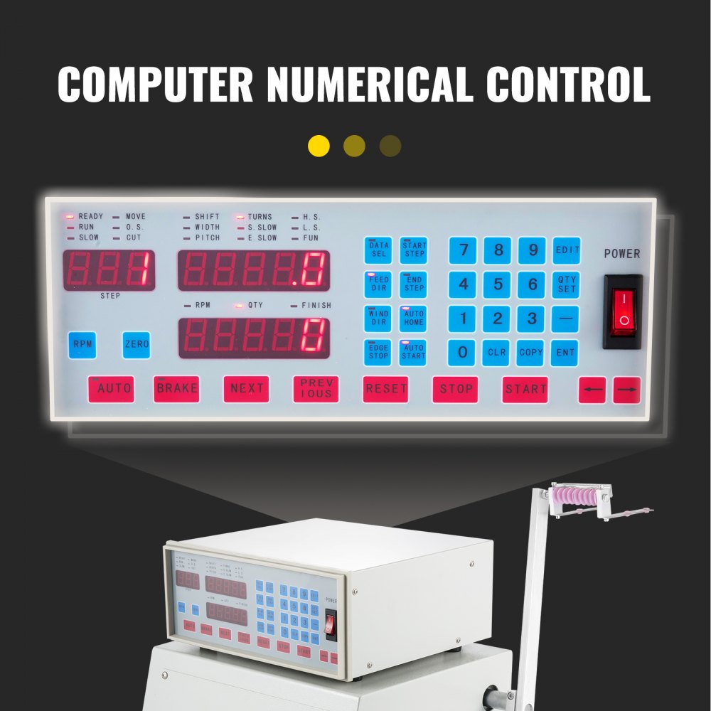
The programming model is worth understanding because it is what gives the machine its flexibility. Memory is organised as up to 1000 winding steps (stored in flash, retained without a battery), and the operator defines a working region by setting a start step and an end step; a coil program is a sequence of steps within that region. Each step carries its own full parameter set — SHIFT (start position), WIDTH (traverse region), PITCH (wire diameter), TURNS (total turns for that step), S.SLOW and E.SLOW (the number of turns to run at low speed at the start and just before the stop of that step), and H.S./L.S. (the high and low winding speeds as a percentage) — plus per-step selections for guiding direction, winding direction (clockwise or counter-clockwise), whether to suspend at the width edges, and whether that step auto-positions and auto-starts. Values can be typed on the keypad or, for the position parameters, taught by jogging the guide. Because each step is independent and steps run in sequence, a multi-section or multi-tap coil is built as a chain of steps: the machine winds one section, stops for the operator to make a tap or change something, and continues into the next step.
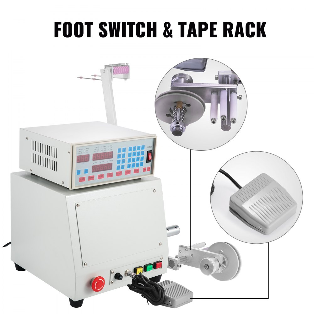
The S.SLOW/E.SLOW ramps deserve a mention because they are what make the machine gentle: it starts each step slowly for the first few turns (so the wire is anchored and up to speed before it accelerates), runs the bulk at high speed, then drops to low speed for the last turns and eases to a controlled stop rather than snapping to a halt at the target turn. That soft start and soft stop is what lets it hit a turn count exactly without overshoot and without shock-loading fine wire. A foot switch is included on many of these machines so the operator can start, pause, and resume with hands free on the wire and the work.
It is worth being clear about what this controller is not, so expectations match the machine. It has no automatic wire cutting or clamping, no toroid shuttle, no programmable multi-axis nozzle, and no closed-loop tension servo — all of which distinguish true industrial winders. What it does provide is the two forms of automation a bench operator most needs: exact, repeatable turn counting and even, programmable traverse. Everything else — threading, tensioning, tapping, insulating, and finishing — remains manual. For a model shop that trade-off is deliberate and correct: the machine removes the tedium and the human error from counting and spacing while leaving the judgement-heavy steps in the operator’s hands, and it does so in a rugged, self-contained box that tolerates the rough power and intermittent duty of a home bench.
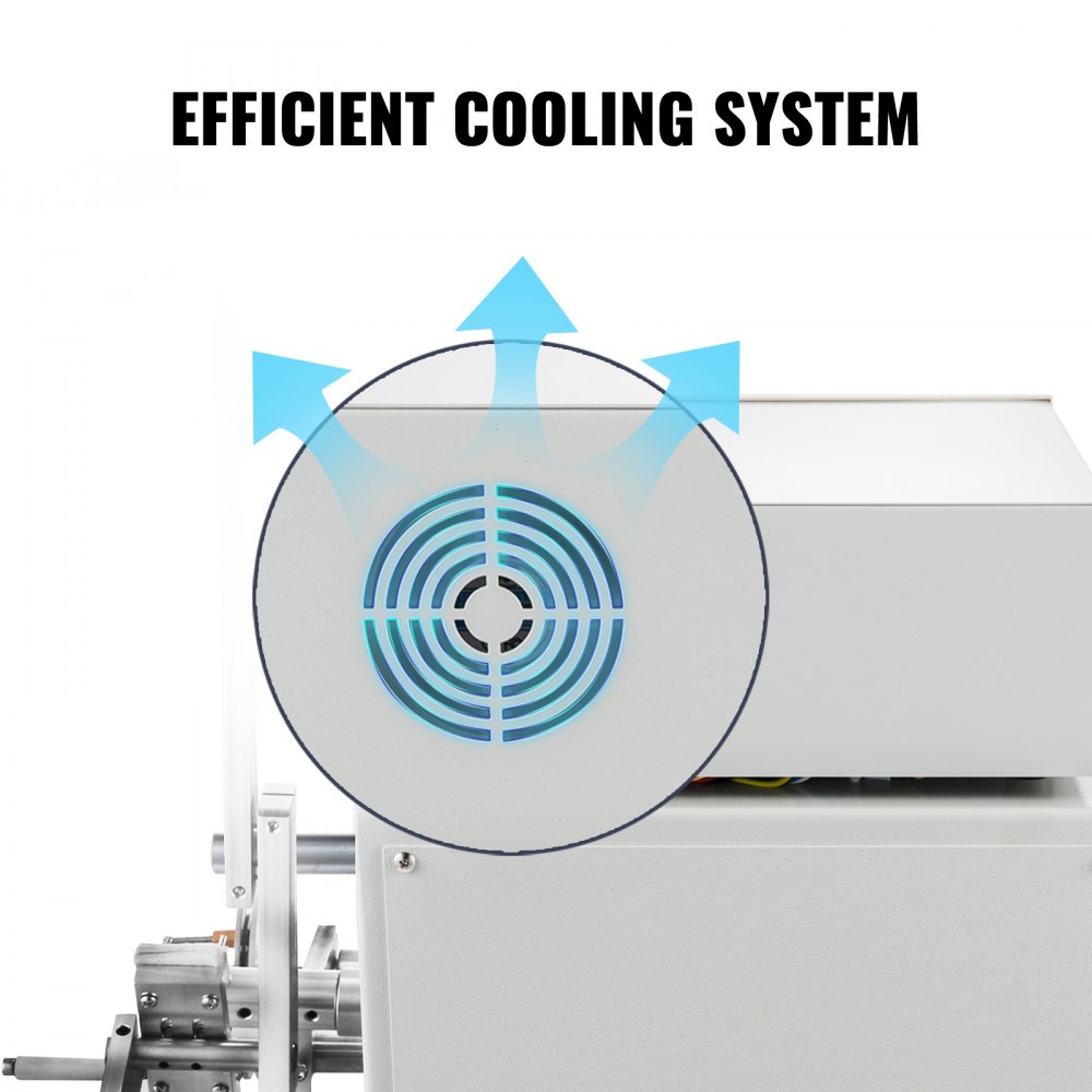
A word on the integrated power and safety hardware, since it lives inside the same control box. The unit accepts single-phase mains (the common versions are wired for either ~110 V or ~220 V, drawing up to roughly 600 VA) and contains its own supply, the spindle brake, and the motor drives, with cooling for the electronics. The spindle brake is significant in practice: it holds the spindle against rotation when stopped, so a paused wind does not unspool under the wire’s tension while the operator makes a tap, and it can be toggled between locked and unlocked from the panel. The CUT wire-break input stops the machine on a broken wire, and the foot switch gives a hands-free stop — between them these are the machine’s everyday safety interlocks, and keeping them functional is part of keeping the machine safe to run.
2.6 How this unit complements winder 1
This machine shares its controller family and its basic spindle-plus-traverse architecture with the shop’s winder 1, so the two are operated the same way and an operator moves between them without relearning. The difference is in how each is standing configured. Winder 2 — the machine in this dive — is set up toward the heavier, wider end of the shared range: dressed with a firmer tensioner for medium and heavy gauge, fitted with arbors for larger bobbins, and left programmed with the shop’s common heavier-coil recipes in its memory region. Winder 1 keeps the fine-wire tensioner and small-former arbors and its own stored programs. Because both controllers retain their programs without power, each machine effectively remembers its own library of jobs, so returning to a repeat wind on either unit is a matter of selecting the stored region rather than re-entering parameters.
The specific tensioner model, arbor set, controller firmware revision, and stored-program contents of the owner’s unit are properties of the physical machine and are recorded as owner’s slots to be filled from it. Volume 3 turns from architecture to procedure: how to mount a bobbin, thread the wire, set turns, pitch, and tension, wind a tapped coil, and verify the result.