CNC Coil Winder 2 · Volume 3
CNC Coil Winder 2 — Using it: setting up and running a wind
3.1 From a spec to a wound coil
Running this machine well is mostly a matter of doing a short sequence of setup steps in the right order and then letting the controller do the counting and spacing it is good at. The sequence is always the same: decide the winding parameters from the coil’s specification, mount and true the bobbin, thread the wire through the tensioner and guide, set the tension, enter or recall the program, wind, and verify. This volume walks that sequence as a working procedure. It assumes the machine architecture from Volume 2 — spindle, traverse, tensioner, CNC-200A-class controller — and it points to the reference dives for the why behind the numbers rather than re-deriving them here.
Two reminders carry over from the earlier volumes. First, the machine’s own plate and control details are recorded as owner’s slots where they can only be read from the physical unit. Second, on this class the tensioner is passive, so the operator owns the tension; the controller owns the turns and the pitch. Keeping that division clear is most of what separates a clean wind from a bad one.
3.2 Reading the spec into machine parameters
Every wind starts by translating the coil’s electrical specification into the handful of numbers the controller actually wants. The specification for a coil typically gives a required inductance or turns ratio, a wire gauge, and the physical bobbin. From those, the operator derives:
- TURNS — the total turn count. For an inductor this comes from the target inductance and the former’s geometry; for a transformer winding it comes from the turns ratio and the reference winding. The derivation itself belongs to the reference dives (the “Coils and coil winding” dive for single coils, the coming “Transformers and transformer winding” dive for ratios and multiple windings); the machine only needs the final number, entered to a tenth of a turn if needed.
- PITCH — set equal to the wire’s overall (enamel-included) diameter for a close-wound layer, or larger for a deliberately spaced winding. The overall diameter, not the bare copper diameter, is what makes turns sit correctly, so a wire table or a quick measurement with a micrometer over a few turns is the right source.
- WIDTH — the axial winding window between the bobbin flanges, which the guide will sweep before reversing for the next layer.
- SHIFT — where along the axis the first turn starts, set so the winding sits where it should on the former.
- Winding direction and any taps — clockwise or counter-clockwise per the coil’s convention, and the turn counts at which intermediate connections must be brought out.
With those in hand the controller work is quick. What takes the time and the care is the mechanical setup, which is where the rest of this procedure focuses.
3.3 Mounting and truing the bobbin
The bobbin or former goes onto the spindle arbor and must be held so it cannot slip axially or rotationally and so it runs true. On this class of machine that usually means sliding the bobbin onto a mandrel sized to its bore and trapping its flanges between a shoulder and a clamping washer or nut. The two things to get right are grip and concentricity. Grip: the bobbin has to turn with the spindle without creeping, because any slip corrupts the turn count silently — the controller counts spindle revolutions, not bobbin revolutions, so a slipping bobbin reads more turns than it actually received. Concentricity: the bobbin should run without visible wobble, because runout modulates the wire tension once per revolution and can push turns off their pitch.
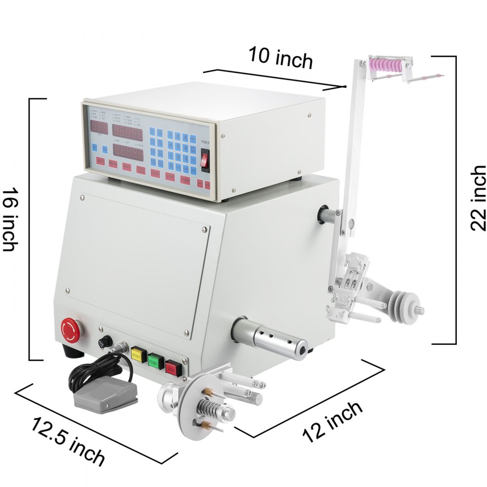
A quick way to check truth is to jog the spindle slowly by hand or at low speed and watch a flange edge against a fixed reference; anything more than a slight wobble means the bobbin is not seated square or the arbor is not the right fit, and it is worth fixing before wire goes on. For odd formers the shop makes an arbor to suit rather than forcing a poor fit — this is one of the standing differences between winder 2 and winder 1, which carry different arbor sets for their different bobbin sizes.
3.4 Threading the wire and setting tension
The wire runs from the supply spool, through the tensioner, through the traverse guide, and to an anchor point on the bobbin. The path should be clean and without sharp kinks, and it should approach the guide squarely so the guide, not the spool geometry, controls where the wire lands.
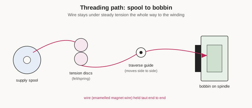
Threading order in practice:
- Seat the wire spool on the dereeler/supply position so it pays off smoothly without the spool overrunning or the wire digging into lower layers.
- Thread the wire between the tensioner’s felt discs (or through its spring path), so the adjustable brake acts on the wire.
- Lead the wire through the traverse guide eyelet, keeping the run from tensioner to guide short and unobstructed.
- Anchor the free end to the bobbin — through a start hole, around a start post, or with a twist and a piece of tape — leaving a lead long enough for the coil’s start connection.
Then set the tension. With a passive tensioner this is done by adjusting the spring pressure on the discs and checking the pull — many operators use a small spring scale, or judge it by hand and by how the first layer packs. The right value depends entirely on the wire: fine wire (tens to a couple of hundred grams for sub-0.2 mm wire) wants a light, sensitive setting, while heavier wire wants a firmer, graduated tensioner. Because winder 2 is kept dressed toward the heavier end of the shop’s range, its tensioner is normally set firmer than winder 1’s; whenever the gauge changes, the tension is re-checked. It is worth winding a few turns and stopping to see how they lie — snug and evenly packed is right; loose and wandering means more tension, and wire that stretches or squeaks means less.
3.5 Entering turns, pitch, tension, and taps
With the machine threaded, the program is entered or recalled. On the CNC-200A class the operator selects the memory region (a start step and end step), enters programming mode, and sets each step’s parameters in turn: SHIFT, WIDTH, PITCH, TURNS, the S.SLOW and E.SLOW soft-start/soft-stop turn counts, and the H.S./L.S. speeds, plus the direction and edge-behaviour selections. Position parameters (SHIFT, WIDTH, travel limits) can be taught by jogging the guide to the actual bobbin rather than typed, which is the fast and reliable way to fit the winding window to the physical former. Each changed value is committed with the enter key before moving on. A repeat job is simply recalled from its stored region — no re-entry needed — which is why the machine’s battery-free program memory is such a practical feature for a shop that winds the same coils more than once.
Taps and multi-section coils are handled by breaking the wind into a chain of steps. The machine winds the first step to its turn count and stops; the operator brings out the tap (leaves a loop or cuts and rejoins with a lead), then the next step continues the winding. Because the controller preserves the fractional part of the turn count across a fixed-point stop, resuming after a tap does not lose the exact position. For a wind that needs an insulating layer between sections, the pause between steps is also where interleaving tape or film goes on — the winding-order and interlayer-insulation reasoning for transformers is covered in the transformer reference dive.
3.6 A worked example: a simple layered inductor
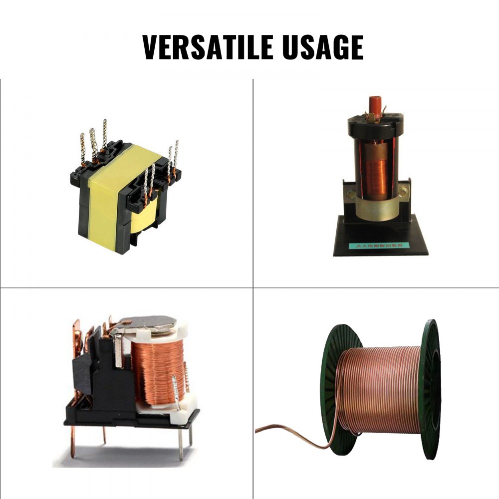
To make the sequence concrete, consider a plain single-winding inductor: say a target that works out to 600 turns of 0.3 mm enamelled wire on a bobbin with a 20 mm winding window between its flanges. The specification-to-parameters step gives TURNS = 600, PITCH = 0.30 mm (the wire’s overall diameter, confirmed on a micrometer), WIDTH taught by jogging the guide to each flange so it reads the true 20 mm window, and SHIFT set so the first turn starts hard against one flange. At 0.30 mm pitch across a 20 mm window the traverse lays roughly 66 turns per layer, so 600 turns builds up as about nine layers — worth knowing, because it tells the operator how tall the finished coil will stand and whether it will clear the flanges.
The setup then runs as above: mount and true the bobbin, thread through the tensioner (set firm-ish for 0.3 mm wire, since this machine is dressed toward the heavier band), lead through the guide, anchor the start with a lead long enough to connect. Program a single step with a few turns of S.SLOW so the start is not shock-loaded and a few of E.SLOW so it eases onto the 600th turn, pick a moderate H.S. rather than the full 6000 rpm, and wind. When it stops on count, the coil is measured on the bench before the leads are dressed: the DC resistance should match 600 turns of 0.3 mm copper at the mean turn length, and the inductance on the LCR meter should land on the design target. If both agree, the leads are finished; if the inductance is low, the usual cause is loose winding (too little tension made the coil bulkier and the turns longer than planned), which is exactly the kind of error the on-machine measurement is there to catch.
3.7 When something goes wrong mid-wind
Two failures interrupt a running wind often enough to plan for. A wire break trips the CUT indicator and stops the spindle; the fix is to rejoin the wire (a small soldered or twisted splice, kept out of the active winding region if the coil’s electrical spec allows, or a restart of the section if it does not), back the tension off if the break was tension-related, and resume. A spool bind or snag — the wire digging into a lower layer on the supply spool, or catching on the dereeler — shows up as a sudden tension spike and often as turns pulling out of place; catching it with the pause control or foot switch before the wire breaks is the reason an operator keeps a hand near the pause during the run. Neither failure need waste the coil if it is caught early, which is the practical argument for winding at a sane speed and watching the wire path rather than walking away.
3.8 Running the wind and verifying the result
Running is deliberately undramatic. The soft-start ramp (S.SLOW) brings the spindle up gently for the first few turns so the anchored start is not shock-loaded, the bulk of the wind runs at the set high speed with the traverse laying each turn one pitch beyond the last, and the soft-stop ramp (E.SLOW) drops to low speed for the final turns and eases to a fixed stop exactly on the target count. The operator’s job during the run is to watch the wire path — that the wire is feeding freely from the spool, that the tension looks steady, and that the turns are landing where they should — and to keep a hand near the pause control (or foot switch) in case the wire snags or the spool binds. The CUT indicator on the controller flags a wire break and stops the wind. Winding speed is chosen for the wire and the tensioner, not maxed out: a passive tensioner sees higher dynamic tension at higher speed, so fine wire and large formers are wound slower.

When the wind finishes, the coil is verified before it leaves the machine. The turn count is trusted from the controller, but the result is checked against the specification: a DC resistance reading confirms the right length of the right-gauge wire went on (resistance scales with turns and inversely with wire cross-section, so a gross error in gauge or count shows up immediately), and an inductance measurement on an LCR meter confirms the coil meets its electrical target. For a transformer, turns ratios are checked by driving one winding with a known AC voltage and reading the others. The measurement techniques and what the numbers should be are the province of the reference dives; the habit that matters at the machine is simply to measure the coil while it is still mounted, so that if something is wrong it can be corrected before the wire is dressed off and the leads are finished.
That is the whole loop: spec to parameters, mount and true, thread and tension, program, wind, verify. Everything the machine automates is inside the wind itself; everything the operator owns is on either side of it. Volume 4 gathers the specifications, maintenance routine, and reference links, and restates the cross-links to the coil-winding and transformer dives.