Prusa MK3S+ · Volume 4
Slicing & Workflow — From Model to Part, Materials, and Maintenance
4.1 The slicer sits between idea and machine
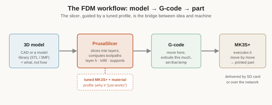
A 3D printer cannot read a 3D model directly. The model — an STL or 3MF file describing the object’s surface as a mesh of triangles, produced in CAD or downloaded from a model repository — describes what the object is, but says nothing about how to build it: how thick each layer should be, how fast to move, how hot to run the nozzle, where to add support, how much of the interior to fill. Bridging that gap is the job of the slicer, and it is the single most important piece of software in the workflow. The slicer takes the model, “slices” it into hundreds of horizontal layers, and for each layer computes the exact toolpath — the sequence of coordinated moves and extrusion amounts — that the printer will follow. Its output is G-code: a long plain-text list of numerical commands (move here, extrude this much, set that temperature) that the printer executes line by line.
4.2 PrusaSlicer and its profiles
The MK3S+‘s companion slicer is PrusaSlicer — free, open-source software that Prusa develops in lockstep with its hardware. (It began as a fork of the venerable open-source Slic3r and has since grown well beyond it.) Its decisive advantage for this machine is that it ships with tuned, tested profiles for the MK3S+ and for Prusa’s own filaments: select the printer, the material, and a quality preset, and the dozens of interlocking parameters that a printer needs are already set to values Prusa validated on the exact machine. This is a large part of why the MK3S+ has a reputation for working out of the box — much of the tuning that a less-supported printer forces onto the user has already been done.
The parameters worth understanding, because they are the ones a maker actually reaches for, group into a handful of families.
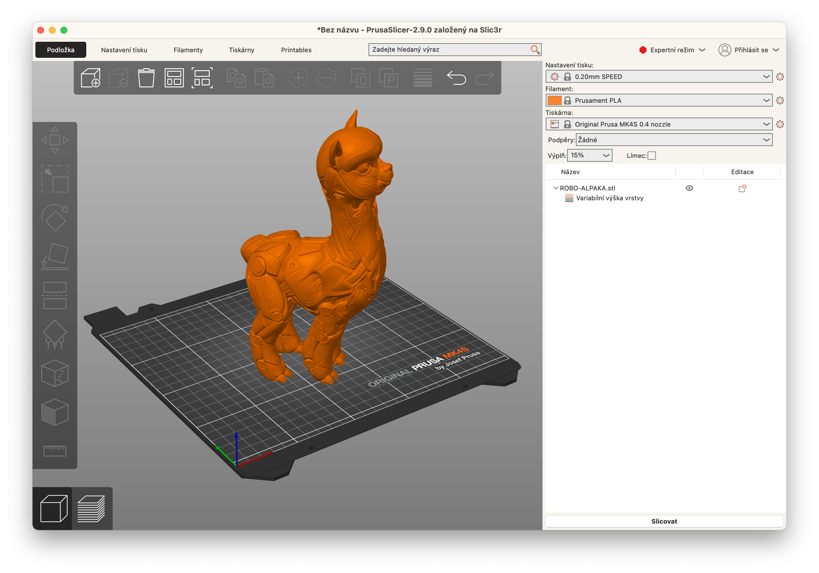
Layer height sets the vertical thickness of each layer and is the master quality-versus-time control. On a 0.4 mm nozzle the MK3S+ prints from about 0.05 mm (very fine, very slow) to about 0.30–0.35 mm (coarse, fast), with 0.15 mm and 0.20 mm as the sensible everyday middle. Thinner layers hide the stair-stepping on curved and sloped surfaces at the cost of proportionally more layers and time. PrusaSlicer bundles these as named presets — the familiar “0.20 mm SPEED,” “0.15 mm QUALITY,” “0.07 mm ULTRADETAIL” and so on.
Infill governs the interior. Few printed parts need to be solid; instead the slicer fills the inside with a periodic lattice, specified as a percentage (typically 10–20% for general parts, higher for load-bearing ones) and a pattern (gyroid and grid being popular general choices). Infill trades material, weight, and print time against strength and rigidity, and choosing it well is one of the main levers a maker has over a functional part.
Perimeters and top/bottom layers set how many solid walls wrap the part. More perimeters mean stronger, more watertight walls; the count and the top/bottom solid-layer count together determine whether infill shows through the surface and how much load the walls can carry.
Supports deal with overhangs. FDM cannot print into thin air — each layer needs something beneath it — so surfaces that overhang beyond roughly 45° from vertical need temporary support structures printed underneath and broken away afterward. The slicer can generate supports automatically, everywhere or only where they touch the build plate, and the art is in using as little as possible: supports cost time and material and leave witness marks, so a part is often best oriented on the bed to minimise the overhangs that need them in the first place.
Speed and temperature settings are mostly inherited from the material profile, but the slicer exposes them for tuning. And a family of quieter, subtler settings — retraction (pulling filament back on travel moves to stop oozing and stringing), cooling-fan behaviour, seam placement, ironing — separate a merely successful print from a clean one.
4.3 Orientation, and the settings that separate good from adequate
Two decisions made before slicing matter more than almost any parameter tweak, and both reward a little thought. The first is orientation — how the part is laid on the build plate. FDM parts are anisotropic: they are markedly stronger within a layer than across the bond between layers, so a bracket that will be loaded in a particular direction should be oriented so that load runs along the layers, not perpendicular to them, where it could peel the layers apart. Orientation also decides which surfaces get the clean top-and-bottom finish, which get the slightly rougher walls, and — as noted — how much support the part needs. A part rotated to stand on its smallest overhanging face often prints faster, stronger, and with less support than the “obvious” flat-on-its-back orientation. Getting orientation right is frequently the difference between a part that works and one that looks fine and snaps in use.
The second is the family of PrusaSlicer features that go beyond the basic presets. Variable layer height lets the slicer print thin, fine layers where a surface is shallow and sloped and thicker, faster layers where it is vertical, buying much of the quality of a fine print at much of the speed of a coarse one. Modifiers let a single object carry different settings in different regions — dense infill only where a bolt passes through, extra perimeters only along a stressed rib. Paint-on supports and paint-on seams give manual control over exactly where supports attach and where the unavoidable per-layer seam falls, hiding it on a back face. None of these is needed for a rough jig, but for a part that must be both strong and clean they are the tools that make the MK3S+ punch above a machine that only knows uniform layers.
4.4 The everyday materials and what each needs
The MK3S+ prints an unusually wide range of materials, and each asks for different bed and nozzle temperatures, different cooling, and — critically — a different bed surface and sometimes an enclosure. A working understanding of the common four or five is most of what a shop needs.
PLA (polylactic acid) is the default and the easy one: it prints cool (nozzle around 210–215 °C, bed around 60 °C), needs no enclosure, sticks well to smooth or textured PEI, and is stiff, dimensionally stable, and pleasant to print. Its weaknesses are heat and impact: a PLA part left in a hot car or a sunlit window will soften and sag, and it is relatively brittle. For prototypes, models, jigs used at room temperature, and anything where ease trumps toughness, it is the right first choice.
PETG (glycol-modified PET, the same polyester family as drink bottles) is the shop workhorse for functional parts. It prints hotter (nozzle around 230–240 °C, bed around 80–90 °C), is tougher and far more heat- and chemical-resistant than PLA, and is only slightly harder to print. Its one quirk matters on this machine: PETG bonds aggressively to smooth PEI — enough to tear the sheet — so it wants a textured/powder-coated sheet or a glue-stick release layer on a smooth one. It also strings more than PLA and benefits from tuned retraction. For brackets, enclosures, fixtures, and parts that must survive some heat or stress, PETG is usually the answer.
ABS and ASA are the true engineering plastics — heat-resistant, tough, machinable, and (for ASA especially) UV-stable for outdoor use. They print hot (nozzle around 240–260 °C, bed around 100 °C) and, crucially, they warp badly as they cool unless the print chamber is kept warm and still. On an open MK3S+ they are frustrating; inside an enclosure (see the modifications volume) they become genuinely usable. They also emit fumes worth ventilating. When a part must take real mechanical or thermal punishment, this is the material class — and it is precisely the class that justifies enclosing a machine.
Flexibles (TPU/TPE) are rubbery filaments for gaskets, bumpers, grips, and flexible fixtures. The MK3S+‘s direct-drive Bondtech extruder handles them better than most printers — the short, well-gripped filament path is exactly what soft filament needs — but they demand slow speeds and careful retraction, and they release best from a textured sheet. Softer grades are harder; the machine’s direct drive is what makes them feasible at all.
Beyond these sit the specialty filaments — the fibre-filled composites for stiffness and strength (which need the hardened nozzle from the previous volume), the dissolvable supports, PVB for vapour-smoothable prints, and the high-temperature engineering plastics that push the very limits of what an open-frame 8-bit machine can do. But PLA, PETG, and ABS/ASA cover the overwhelming majority of real shop work.
4.5 First-layer calibration and getting adhesion right
Almost every print failure that is not a slicing mistake traces back to the first layer, so it is worth being methodical about it. Two independent things must be right: the mesh (the bed’s shape, measured automatically by the SuperPINDA before each print, as covered earlier) and the Live Z offset (the single number that sets how close the nozzle rides to the bed on that first layer). The mesh is handled by the machine; the Live Z is set once, by hand, by the operator.
The calibration procedure is simple and worth doing carefully: run the machine’s first-layer calibration, watch the first layer go down, and adjust the Live Z live with the knob until the extruded lines are pressed lightly into each other with no gaps between them and no ridges standing proud. Too high and the lines sit as separate round strands that peel up; too low and the nozzle drags, squashes the plastic into translucent ridges, and can starve extrusion. The target is a smooth, matte, uniform sheet with the neighbouring lines just merged. Once dialled in for a given sheet, the offset holds — the SuperPINDA’s temperature independence is what lets it stay put — though swapping to a sheet of different thickness (a textured sheet is not the same thickness as a smooth one) means a small re-check.
Adhesion beyond that comes down to a clean bed above all: PEI grips well only when free of skin oils and fingerprints, so a wipe with isopropyl alcohol between prints is the highest-value habit in 3D printing. Warp-prone materials benefit from a brim (a flat skirt of extra first-layer perimeters that widens the part’s grip on the bed) or a raft, from disabling drafts, and from the right sheet. When a first layer still will not stick, the fault is nearly always dirty PEI, a Live-Z set too high, or the wrong sheet for the material — in that order.
4.6 Common failure modes and their fixes
A handful of failures account for most ruined prints, and each has a well-understood cause, which is one more reason the MK3S+ is a comfortable machine to learn on.
- First layer won’t stick / part detaches. Dirty bed, Live Z too high, wrong sheet, or warp-prone material without an enclosure or brim. Clean the PEI, lower Live Z slightly, add a brim, match the sheet.
- Stringing and blobs. Fine hairs strung between features, usually PETG or a too-hot nozzle or too-little retraction. Dry the filament, drop the temperature a few degrees, tune retraction.
- Warping and layer splitting. Corners curling up or a tall part cracking along a layer line — the signature of ABS/ASA (or large PETG) cooling unevenly. Enclose the machine, raise the bed temperature, reduce or redirect part cooling.
- Under-extrusion / gaps. Thin, gappy walls and weak parts. A partial nozzle clog, a worn nozzle, wet or brittle filament, or an extruder slipping — clean or replace the nozzle, dry the filament, check the Bondtech gears.
- Clogs and heat-creep jams. The extruder stops feeding mid-print, often because the heatsink fan stopped and heat crept up the path. Clear the jam (a cold-pull often works), and always confirm the hotend fan is running.
- Ghosting / ringing. Faint echoes downstream of sharp corners — the bed-slinger’s moving mass again. Slow down, tighten belts, and don’t fight physics.
Because the community has documented every one of these exhaustively and every relevant part is available, a MK3S+ failure is a puzzle with a known answer far more often than a mystery.
4.7 Routine maintenance
A well-maintained MK3S+ drifts very little, and the maintenance list is short and mostly infrequent.
The smooth rods and leadscrews want a light film of the correct lubricant periodically — a PTFE or lithium grease on the linear-bearing rods and a suitable lubricant on the Z leadscrews — wiped clean and re-applied rather than piled on, since grit trapped in old grease does more harm than dry rods. Belt tension on X and Y should be checked occasionally; the firmware can report a belt-status figure, and a belt that has stretched or loosened shows up directly as dimensional error and ringing. The SuperPINDA height — the probe’s vertical position relative to the nozzle tip — is set during assembly and rarely needs attention, but a first layer that has mysteriously gone wrong across the whole bed (rather than in one spot) is worth checking against it. The nozzle is a consumable: it wears, especially on abrasive filaments, and a worn or clogged nozzle is a ten-minute swap (heat, unscrew, replace, and re-set the Live Z offset afterward, since a new nozzle may seat at a slightly different height). Keeping the PEI sheet clean with isopropyl alcohol, keeping filament dry (hygroscopic materials like PETG, ABS, and especially nylon and TPU absorb moisture from the air and print poorly when wet), and periodically checking that all the fans spin freely round out the routine. None of it is onerous, and a machine kept to it will run for years — which, across two units in steady shop use, is exactly the point.
Comments (0)