Shapeoko 3 XXL · Volume 2
The Machine in Detail — Frame, Motion, Motors, and the Cutting End
2.1 Reading the machine as a structure
Every CNC machine is a compromise between three things it can never fully have at once: a large work area, high rigidity, and low cost. Pick any two. The Shapeoko 3 XXL picks work area and cost, and understands its own rigidity limits well enough to be useful anyway. To use it well — and to understand why its owner modified it the way he did — it pays to look at each part of the structure and ask what it does, what it gives up, and where it flexes.
The whole machine is a chain of parts between the spinning cutter and the workpiece, and that chain is only as stiff as its weakest link. Play in a V-wheel, stretch in a belt, flex in the gantry beam, slop in the router mount — each adds up as unwanted movement between tool and part, which shows in the cut as chatter marks, lost dimensional accuracy, or a snapped endmill. Walking the chain from the frame outward is the clearest way to understand the machine.
2.2 The frame
The Shapeoko’s frame is built from aluminium extrusion — structural profile with slotted faces and, importantly, precisely machined edges that double as running surfaces for the motion system. On the XXL, two long extrusions form the left and right rails of the machine, front and rear extrusions tie them into a rectangle, and the whole assembly bolts together with the slotted faces carrying T-nuts wherever something needs to be attached. It sits on adjustable feet so the frame can be levelled and, more importantly, kept from twisting on an uneven surface.
The frame is what defines the machine’s footprint. The XXL’s cutting area of roughly 33 by 33 inches (about 838 by 838 millimetres) sits inside an overall footprint of approximately 44.75 inches wide by 40.25 inches deep, standing about 16 inches tall, with the electronics enclosure projecting a little beyond the left rail. The assembled machine weighs on the order of 145 pounds — heavy enough to stay put in use, light enough that two people can move it, and a useful reminder that this is not an industrial casting. Anyone planning an enclosure or cabinet needs to allow generously beyond those numbers for cable runs, dust hoses, and access, a point that becomes very relevant in the modifications volume.
Extrusion frames have a specific personality. They are stiff in compression and tension along their length, but a bolted rectangle of extrusion can rack — twist out of square — if it is not kept flat and its joints stay tight. A great deal of what keeps a Shapeoko cutting accurately is simply keeping the frame flat, square, and unstressed on its base. This is one reason a purpose-built, rigid cabinet is such a popular upgrade: a machine that sits flat and undisturbed holds its geometry far better than one perched on a wobbly bench.
2.3 The gantry and the three axes
The Shapeoko uses a moving-gantry layout, and understanding it is the key to understanding everything the machine does.
Picture the rectangular frame lying flat, with the workpiece held down in the middle. Spanning the machine from left to right is the gantry — a beam that carries the cutter. This gantry rolls forward and backward along the two long side rails: that motion is the Y axis. Riding along the gantry beam, left to right, is the carriage that holds the router: that motion is the X axis. And the router itself moves up and down on the carriage: that is the Z axis. Between them, the three axes let the cutter reach any point in a rectangular box above the bed.
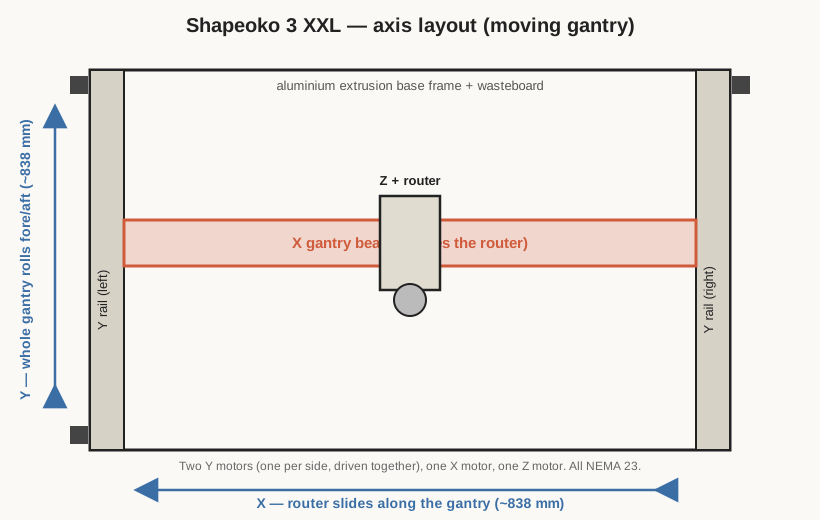
Because the gantry spans the full width of the machine and must move as one piece, the Y axis is driven by two motors — one on each side rail — wired to move together so the gantry advances squarely rather than skewing. The X axis has a single motor pulling the carriage along the beam, and the Z axis has a single motor of its own. Four motors in total, three logical axes.
The XXL’s large format stresses this layout in a predictable way. The gantry beam on the XXL is the same beam used on the smaller machines, but it does not need to be longer — the XXL grows in the Y direction (longer side rails) and the X is already the full 33 inches. The long unsupported span of the X gantry beam is where a large open-frame router shows its flex: push a cutter hard in the middle of a long beam and the beam bows a little, and the cut suffers. This is inherent to the design and is managed by taking lighter cuts, not by wishing the beam were stiffer.
2.4 The V-wheel motion system
Here is where the Shapeoko diverges most sharply from an industrial machine. There are no ground steel linear rails in the stock Shapeoko 3. Instead, each moving carriage rides on V-wheels: hard polymer wheels (Delrin or a similar engineering plastic) with a 90-degree V groove machined into their rim. The V groove rides directly on the machined edge of the aluminium extrusion, so the extrusion itself is the rail.
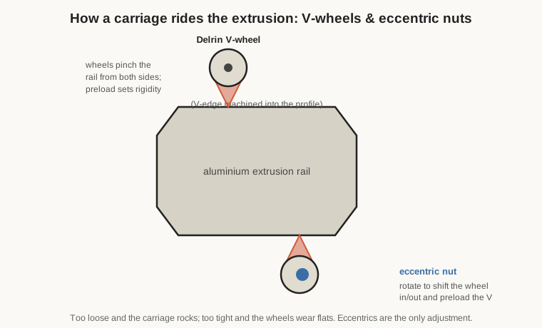
Each carriage has several V-wheels arranged so they pinch the rail from both sides, holding the carriage captive while letting it roll freely along the rail’s length. Some of those wheels mount on plain bolts; others mount on eccentric nuts — nuts whose bolt hole is offset from centre, so that rotating the nut moves the wheel slightly toward or away from the rail. This is the only adjustment in the whole motion system, and it is the one every Shapeoko owner learns to feel by hand. Set the eccentrics too loose and the carriage rocks, adding play straight into every cut. Set them too tight and the wheels are crushed against the rail, wearing flat spots and dragging the motors. The correct setting is snug — no perceptible rock, but the wheel can still just be stopped from spinning by a fingertip while the carriage moves.
V-wheels are a brilliant piece of cost engineering. They are cheap, quiet, tolerant of dust, need no lubrication, and are trivially replaceable. They are also, unavoidably, less rigid and less precise than a preloaded linear rail, and they wear. For wood and plastic at sensible feeds, they are entirely good enough, and millions of parts have been cut on them. For the most demanding work, they are the first thing a builder looks to upgrade — and, notably, the popular Z-axis upgrades replace the V-wheel Z with a proper linear-rail-and-screw arrangement, which is exactly the path this machine’s owner took.
2.5 The belt drives
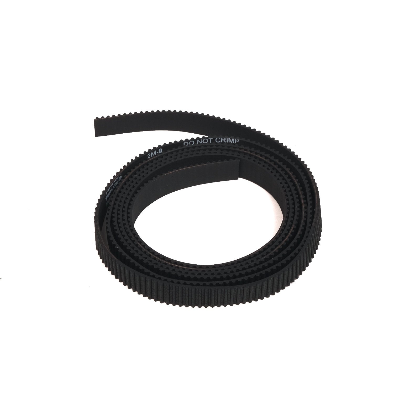
Motion along X and Y is produced by GT2 toothed belts, 9 millimetres wide. GT2 is a belt-and-pulley tooth profile designed for positioning rather than power transmission: its rounded teeth mesh cleanly with a toothed pulley and locate accurately with minimal backlash. On the Shapeoko, each axis has a long belt fixed at both ends to the frame, running past idler pulleys and around a toothed pinion on the stepper motor. As the motor turns, its pinion walks along the stationary belt, dragging the carriage with it.
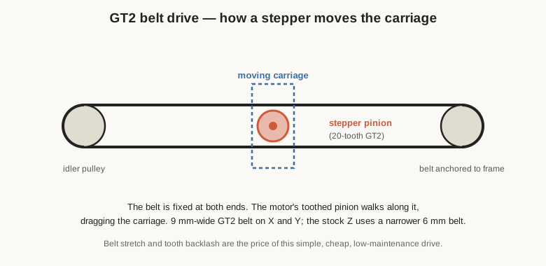
Belt drive is the heart of the Shapeoko’s cost-and-simplicity bargain, and it has real virtues: it is cheap, quiet, backlash-free at the tooth mesh, forgiving of debris, and needs no lubrication. It also has two honest weaknesses. First, a belt is elastic — it stretches under load, so when the cutter pushes back against the direction of travel, the carriage gives a little and springs back, which shows up as positional error and can feed chatter. The longer the belt, the more total stretch, which is why the XXL’s long axes feel slightly softer than a smaller Shapeoko’s. Second, belt drive on a vertical axis is a particular liability: on the stock belt Z, the belt must not only position the router but hold its whole weight against gravity, and any belt stretch translates directly into the cutter plunging slightly deeper than commanded under cutting load. Correct belt tension — firm and even, without over-stressing the motor shafts — mitigates all of this, and is a standing maintenance item. But the fundamental softness of a belt Z is the single biggest reason owners convert to a screw-driven Z, as this machine’s owner has done.
2.6 The stepper motors
All four axes are driven by NEMA 23 stepper motors. NEMA 23 is a frame-size designation — the motor’s mounting face is 2.3 inches square — and these are meaty motors by hobby-CNC standards, noticeably larger than the NEMA 17 units common on 3D printers. They are bipolar stepper motors that move in discrete 1.8-degree steps, meaning 200 full steps per revolution, and the controller can subdivide those further with microstepping for smoother motion.
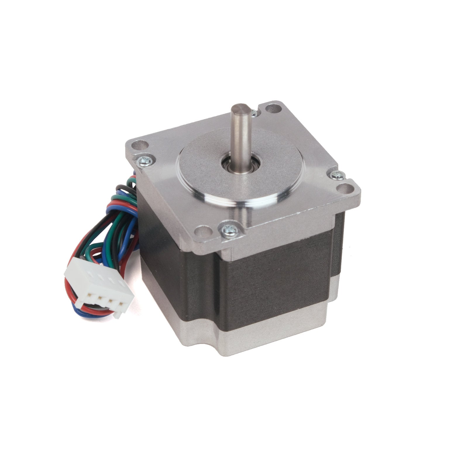
The important thing about steppers is that they run open-loop: there is no encoder feeding position back to the controller. The controller commands a number of steps and simply trusts that the motor took them. This is cheap and, within limits, perfectly accurate — a stepper that is not overloaded lands exactly where it is told, every time. The failure mode is lost steps: if the cutter jams, a belt slips, or the machine is asked to accelerate a load harder than the motor can manage, the motor skips steps, the controller never knows, and every subsequent move is offset by that error. On a lost-step job the part is usually ruined and the machine must be re-homed. Almost everything about running a Shapeoko sensibly — appropriate feeds, shallow cuts, correct belt tension, clean rails — is ultimately about never asking the motors for more than they can deliver, so they never lose a step.
2.7 The router mount and spindle options
The cutting spindle on a Shapeoko is a trim router — a compact, high-speed router motor — clamped into a 65-millimetre-diameter mount on the Z carriage. Two options dominate.
Carbide’s own Carbide Compact Router is a variable-speed trim router sold specifically for the machine, running from roughly 12,000 to 30,000 RPM. It drops straight into the 65 mm mount and takes precision collets.
The other near-universal choice is the DeWalt DWP611, a compact fixed-base router with a 1.25-horsepower motor and variable speed from about 16,000 to 27,000 RPM. It is a well-made, widely available tool with a large accessory ecosystem, and it fits the 65 mm mount directly. Many owners prefer it for its build quality and the availability of parts.
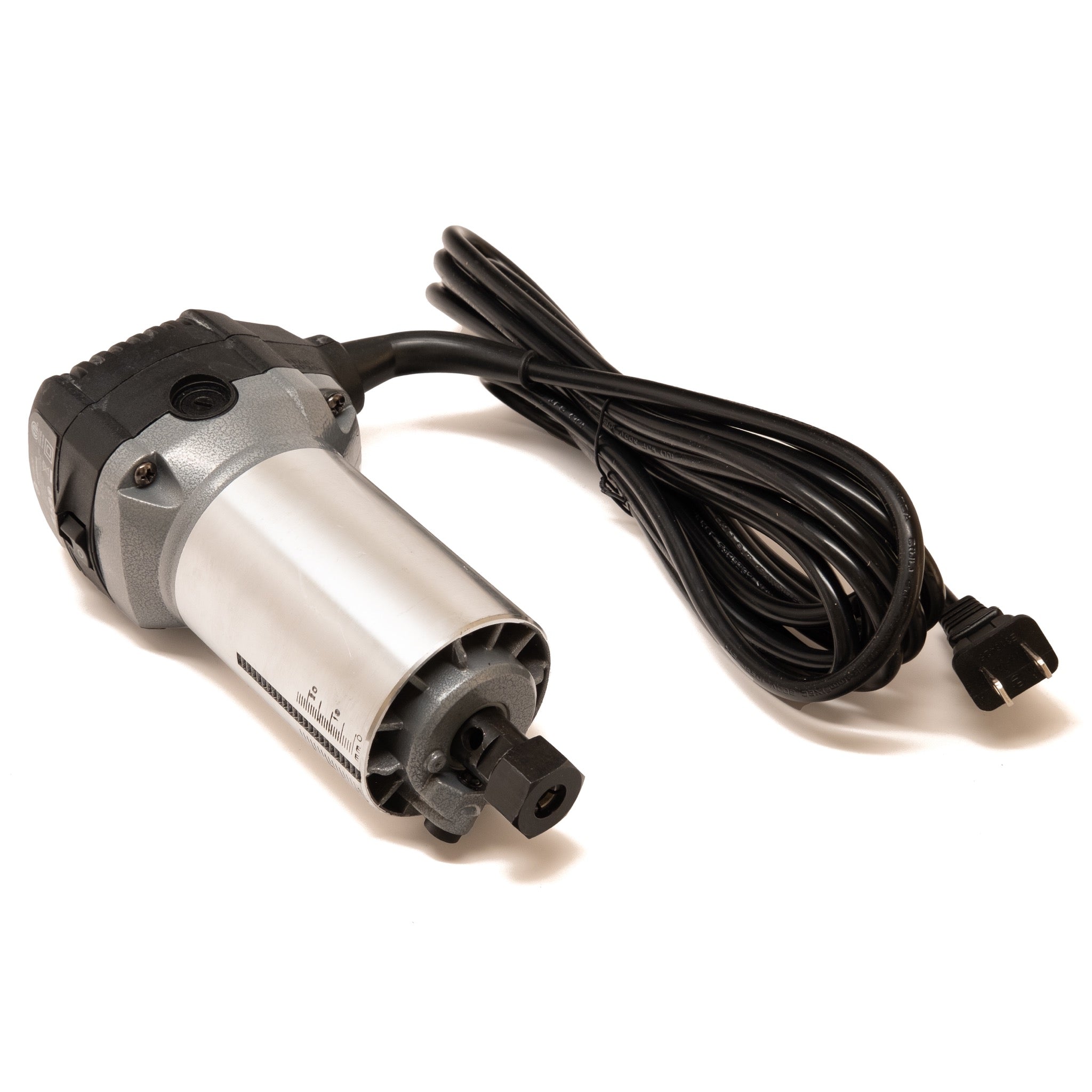
Both routers take standard 1/4-inch and 1/8-inch collets, which covers the great majority of hobby endmills and router bits. The distinction worth understanding is that a trim router is not a true spindle. A trim router has brushes, a fixed and fairly high minimum speed, a noise signature to match, and no automatic speed control from the machine — the operator sets the speed with a dial. A proper CNC spindle (typically an air- or water-cooled AC unit driven by a variable-frequency drive) runs quieter, holds speed under load, starts far lower in RPM, and can be commanded by G-code. Fitting a spindle is a common Shapeoko upgrade for exactly those reasons, though it brings its own weight, cost, and control complexity. The stock trim-router approach keeps the machine simple and cheap, at the cost of noise and a lack of speed control.
2.8 The wasteboard and workholding surface
Beneath the cutter sits the wasteboard — a sacrificial sheet, usually MDF, bolted to the frame. Its job is twofold: to give a flat, known reference surface for the bottom of the workpiece, and to be the thing the cutter bites into when a cut breaks through the stock, so the machine’s real structure is never damaged. Wasteboards are consumable by design; when one gets too chewed up or loses flatness, it is resurfaced or replaced.
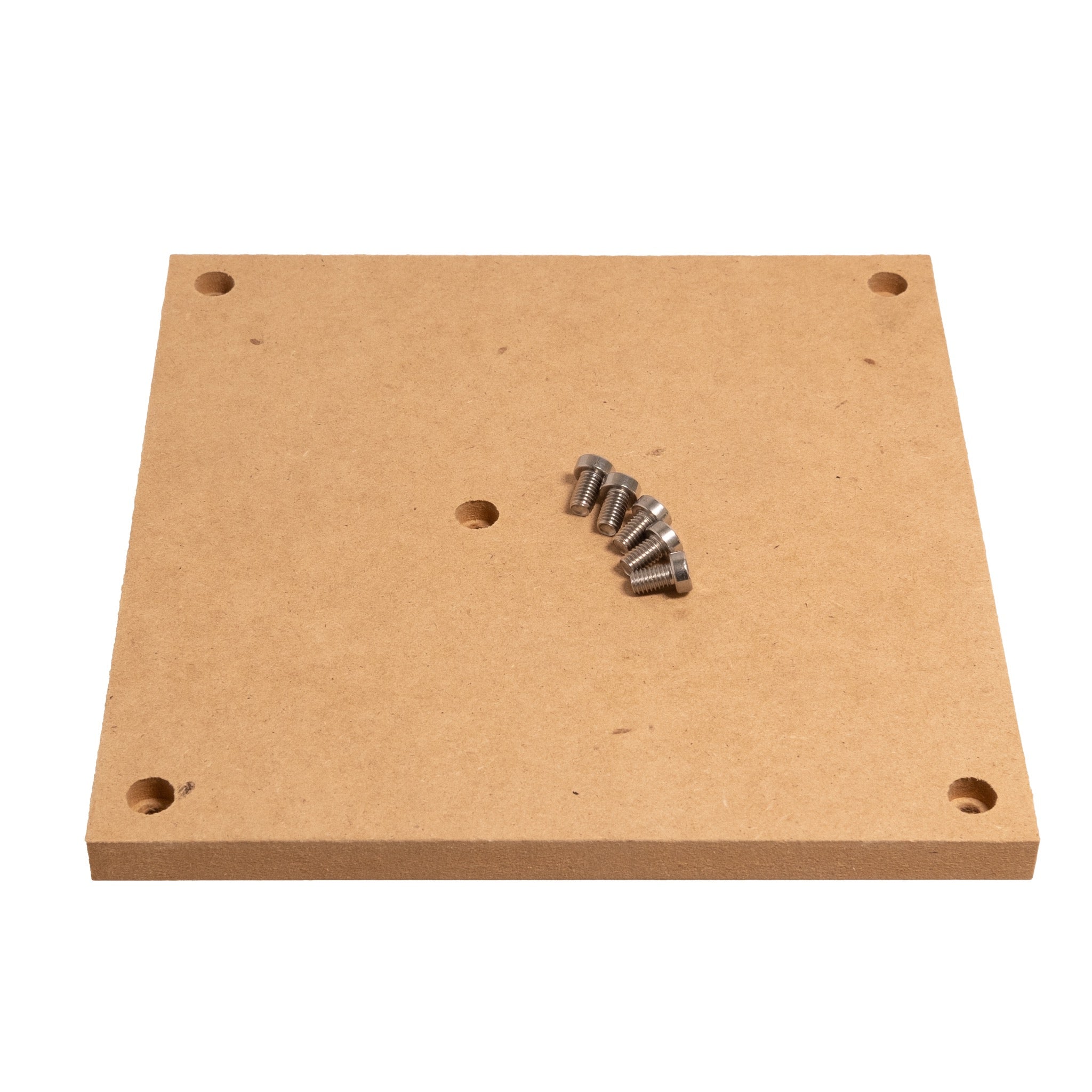
On the XXL, the wasteboard is a large expanse, and how it is fitted for clamping matters. Common approaches include threaded inserts on a grid, into which clamps and hold-downs bolt, or T-slot tracks — extruded aluminium channels let into the surface that accept T-bolts anywhere along their length. The XXL’s stock arrangement provides parallel tracks that accept 1/4-inch T-bolts, giving a flexible clamping grid across the big bed. Whatever the scheme, the golden rule is that the wasteboard must be flat and coplanar with the machine’s motion — which is why owners surface the wasteboard by having the machine itself skim the top face flat with a large bit, a procedure covered in the using-it volume. A wasteboard that is flat relative to the machine turns the whole bed into a reliable reference; one that is not quietly ruins the accuracy of every job.
2.9 The rigidity reality, summed up
Put the chain back together and the picture is coherent. The Shapeoko 3 XXL is an extrusion frame that can rack if not kept flat; a long gantry beam that bows a little under hard cutting; carriages that ride on preloaded polymer V-wheels with a small, adjustable amount of play; belt drives that stretch slightly under load, most consequentially on the vertical Z; and open-loop steppers that will silently lose steps if pushed past their limit. None of these is a flaw so much as a design choice in service of a large, cheap, buildable machine.
The practical consequence is a machine that is superb at what it is asked to do gently and large — signs, panels, jigs, wood and plastic parts — and that rewards a light touch, good workholding, and attention to the few adjustable joints in the chain. It is also a machine whose weak links are well understood and, one by one, addressable: stiffen the frame with a good cabinet, replace the softest drive (the belt Z) with a screw, and tighten up the electronics and control. Those are precisely the modifications the next volumes turn to — first the controller and software that command all this motion, then the three physical upgrades that transform this particular machine from a stock XXL into the one that lives in this shop.
Comments (0)