Shapeoko 3 XXL · Volume 5
Using It — Workholding, Bits, Feeds and Speeds, and the Path from Model to Part
5.1 From owning to operating
Everything so far has been about what the machine is. This volume is about what it takes to get good parts out of it, which is a different and more practical body of knowledge. A CNC router does exactly what it is told, which means the quality of the result is set almost entirely by the setup: how the work is held, which bit is chosen, how fast it is fed, and whether the machine is square and flat. Get those right and the machine is a joy; get them wrong and it will faithfully, precisely, ruin a part or throw it across the enclosure. None of it is hard, but all of it rewards understanding rather than guessing.
5.2 Workholding: the first thing that goes wrong
The most common way a job fails is not a software error or a broken bit; it is the workpiece moving. A router bit pushes on the work with real force, and that force changes direction as the cutter goes around a part — pulling the stock toward the bit here, away from it there, lifting it as the flutes climb. Workholding has one job: to keep the stock exactly where it was zeroed, against the worst pull the cut can produce, while never putting anything the cutter will hit in the cutter’s path. On a large open-frame machine, where the work is often big and flat, this is a craft in itself.
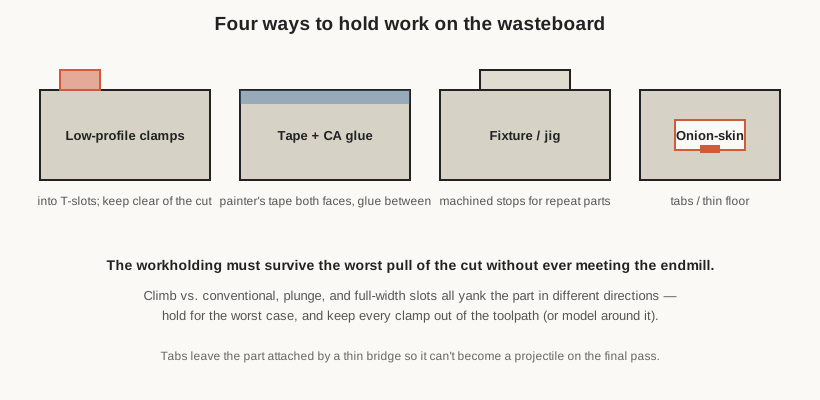
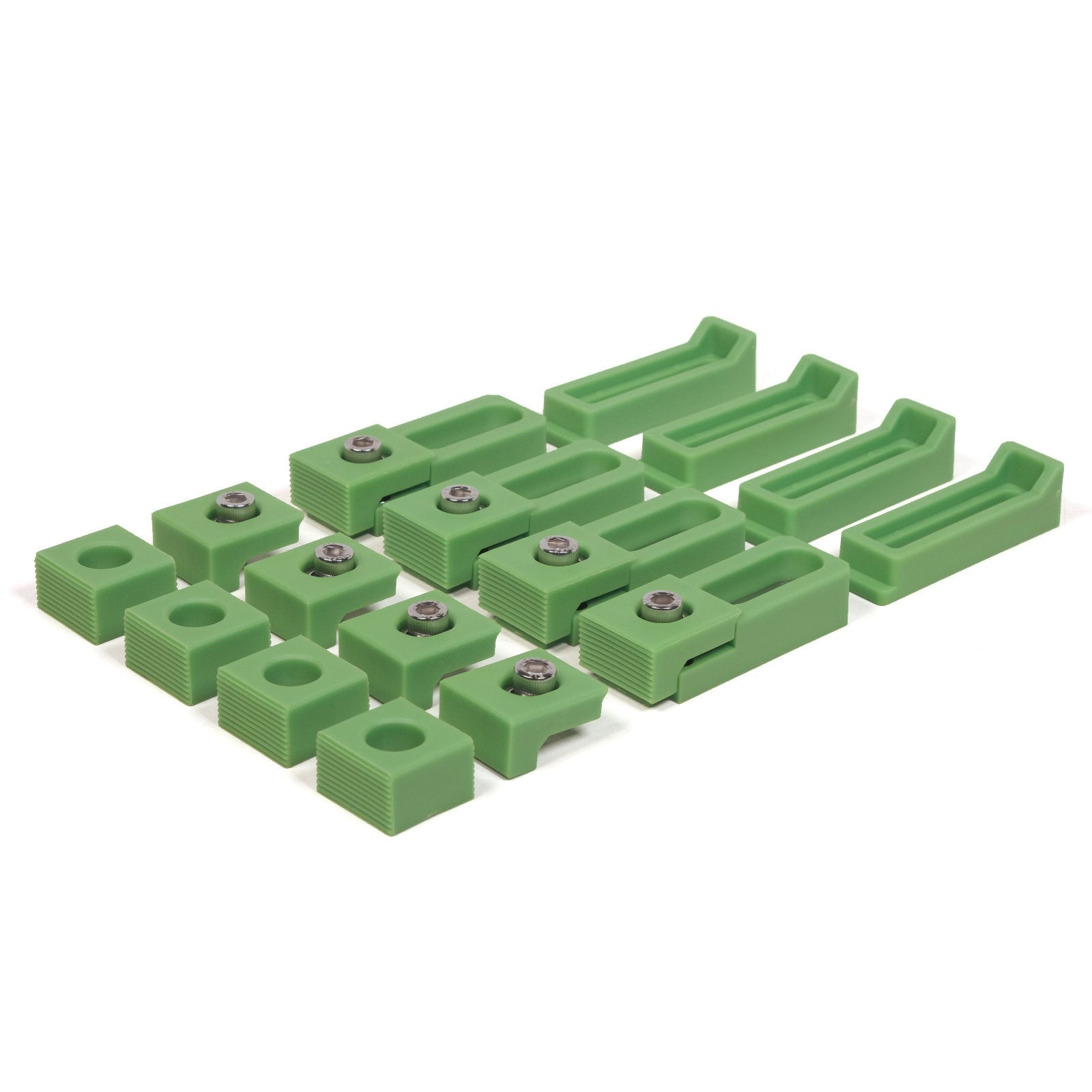
Mechanical clamps are the obvious method: low-profile clamps or hold-downs bolted into the wasteboard’s T-slots or threaded inserts, pressing the stock down and in. Low profile matters — a tall clamp is something the gantry or router can collide with — and clamps must be placed where the toolpath never reaches them, or the job must be planned around them. Carbide and others sell dedicated low-profile clamp sets for exactly this.
Painter’s tape and CA glue is the trick every router user learns. A layer of blue painter’s tape is burnished onto the wasteboard and another onto the bottom of the stock; a few drops of cyanoacrylate (superglue) between the two tape layers bond them fiercely, while the tape peels cleanly off both surfaces afterward. It holds flat stock down across its whole area with nothing standing proud for the cutter to hit — ideal for parts that would be awkward to clamp, or where clamps would foul the cut. For large flat panels on the XXL it is often the method of choice.
Fixtures and jigs come into their own for repeat work. A fixture is a purpose-made holder — often itself cut on the machine — with stops and clamps that locate identical parts in the same place every time. For a batch of the same part, or for holding an awkward shape, a fixture turns setup from a per-part fiddle into a drop-in operation. That the machine can make its own fixtures is one of the quiet pleasures of owning a CNC router.
Tabs, finally, are less a holding method than an anti-escape measure. When a profile cut goes all the way through the stock, the part it frees can shift or lift into the cutter on the final pass. Leaving small tabs — thin bridges of uncut material joining the part to the surrounding stock — or a thin onion-skin floor keeps the part captive until it is deliberately cut or snapped free by hand afterward. It is cheap insurance against a finished part becoming a projectile.
5.3 Bits and endmills: choosing the cutter
The cutter is where the machine meets the material, and choosing it well is half of getting a clean result. Router and CNC cutters come in a bewildering variety, but a few distinctions carry most of the decisions.
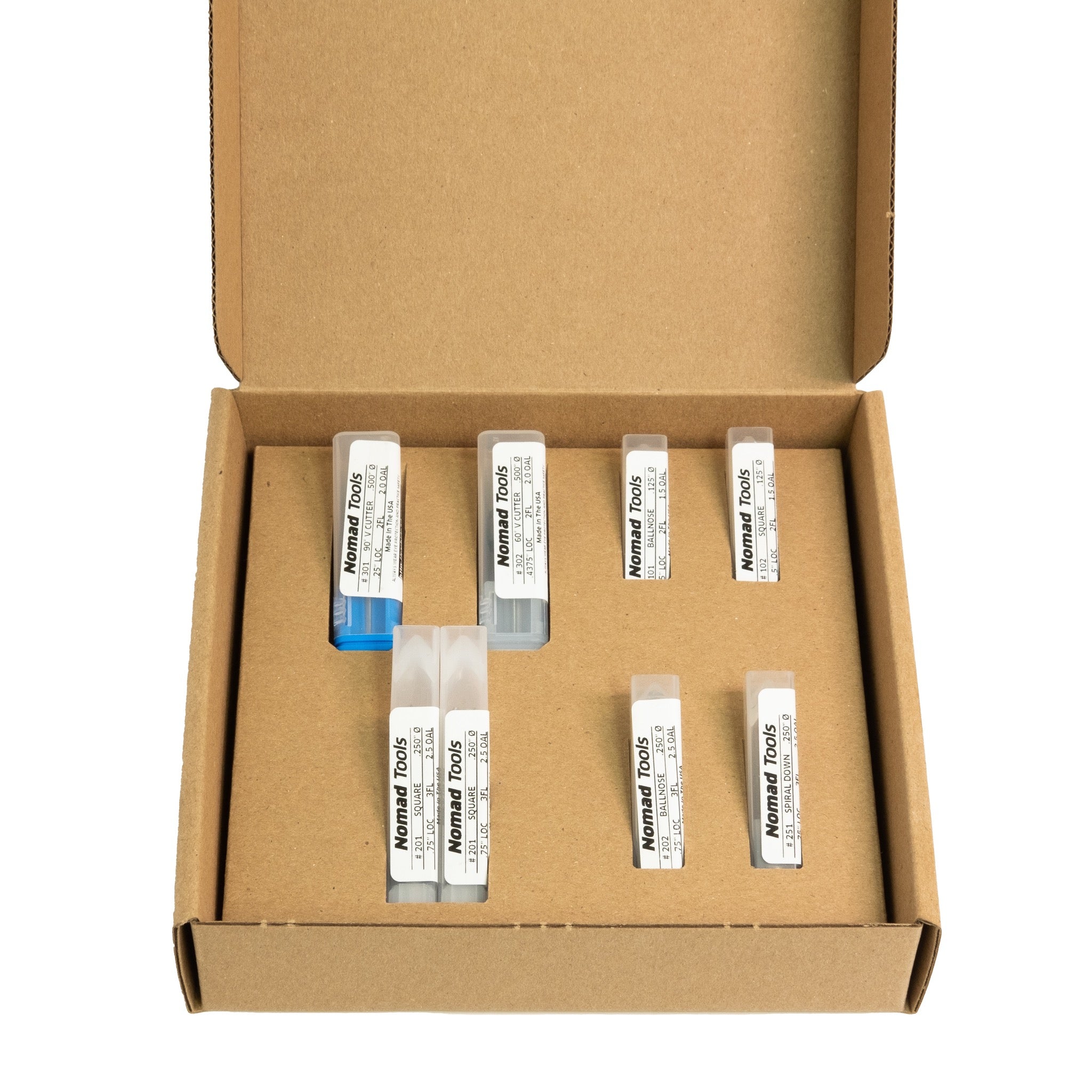
Diameter sets both the finest detail the bit can produce and how much abuse it can take. A large-diameter bit is stiff and clears material fast but cannot cut a tight internal corner; a small bit reaches fine detail but is fragile and must be fed gently. Common CNC-router work lives around 1/8-inch and 1/4-inch bits, which the standard collets accept directly.
Flute count trades finish against chip clearance. More flutes give a smoother finish but leave less room to eject chips, which matters enormously in materials like aluminium and plastic that clog and melt. Fewer flutes — often a single flute — clear chips aggressively and run cooler, which is why single-flute bits are the standard advice for aluminium and many plastics on a light machine.
Geometry is the rest of the story. An up-cut bit augers chips upward out of the cut (great clearance, but it can lift and fray the top surface); a down-cut bit pushes chips down (leaving a clean top edge, but clearing chips poorly in a deep pocket); a compression bit does both, clean on top and bottom, prized for plywood. A ball-nose bit has a rounded end for 3D contouring and carving. A V-bit cuts a sharp V-groove and is the tool behind V-carved lettering and decorative work — a genuine sweet spot for this machine. Matching bit geometry to the job is one of the biggest levers on cut quality.
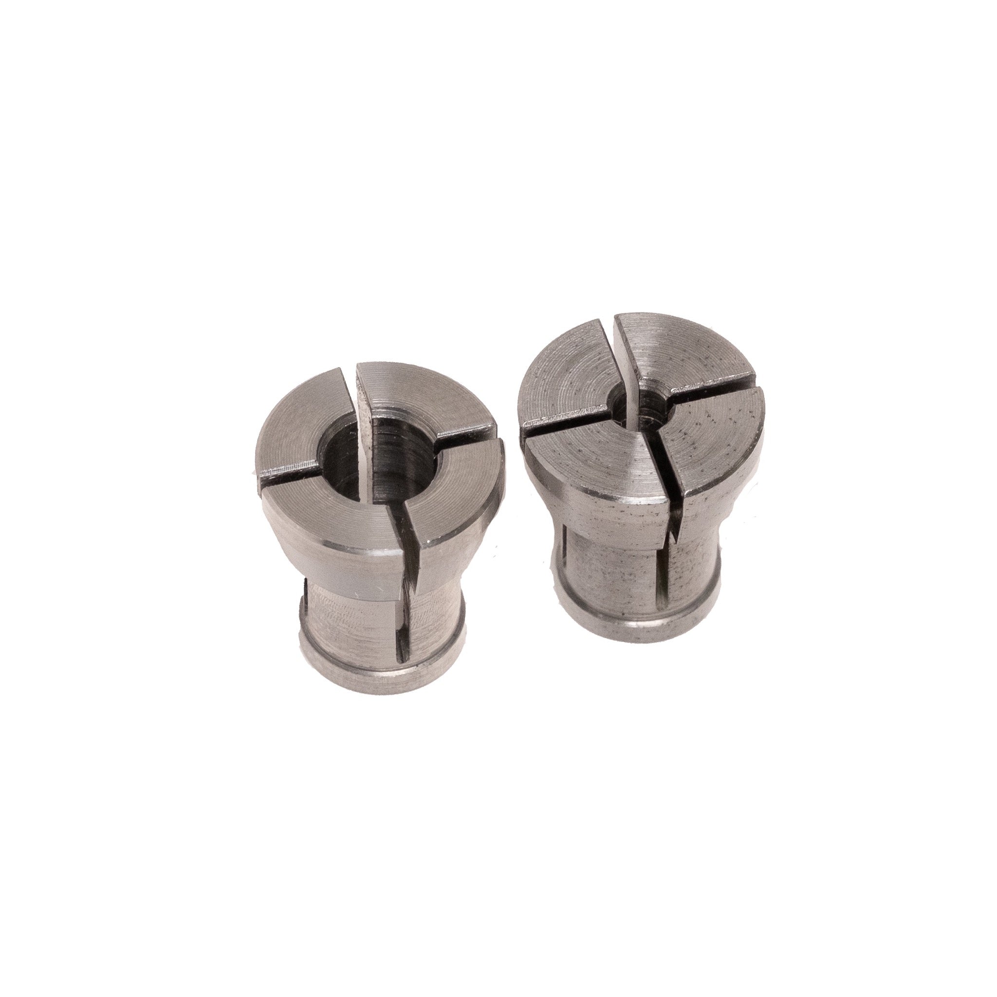
A word on collets: the collet is the split sleeve that grips the bit’s shank in the router. It must match the shank diameter exactly (a 1/8-inch bit needs a 1/8-inch collet, not a 1/4-inch collet with a reducer sleeve unless that sleeve is designed for it), must be clean, and must be seated and tightened correctly. A worn, dirty, or mismatched collet grips poorly, runs the bit out of true, and in the worst case lets the bit creep or fly loose. It is an unglamorous part that quietly governs accuracy.
5.4 Feeds and speeds: the one calculation that matters
If there is a single concept that separates people who fight their router from people who enjoy it, it is feeds and speeds — and beneath that headline, one idea does most of the work: chip load.
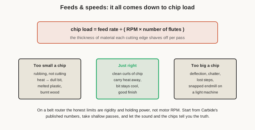
Chip load is the thickness of material each cutting edge removes on each pass, and it is set by the relationship between three numbers: the feed rate (how fast the machine moves the cutter through the work), the spindle speed (RPM), and the number of flutes. The relationship is simply chip load = feed rate ÷ (RPM × flutes). It matters because a cutting edge wants to take a chip, not a smear. Too small a chip and the edge rubs instead of cutting, generating heat that dulls the bit, melts plastic, and burns wood. Too large a chip and the cutter deflects, chatters, and on a light machine either loses steps or snaps. Between those extremes is a window where the bit peels clean chips that carry the heat away with them, leaving a good finish and a cool, long-lived cutter.
The counter-intuitive lesson for beginners is that going too slow — dialling the feed down out of nervousness while leaving the router screaming at full RPM — is often what burns bits, because it drives the chip load below the rubbing threshold. The fix is frequently to feed faster or slow the RPM, not slower. On a trim-router-equipped Shapeoko this is complicated slightly by the router’s high minimum speed: these routers will not run slow, so for materials that want low RPM (aluminium especially), the feed has to come up to keep the chip load sane.
The honest way to approach feeds and speeds on this machine is to start from Carbide’s published numbers for the material and bit (their CAM software encodes sensible defaults), take shallow depths of cut, and then read the machine: the sound of a happy cut, the size and colour of the chips, the absence of chatter marks and burning. The real limits on a belt router are not the motor’s top speed but the machine’s rigidity and the workholding’s grip — so the safe direction of experimentation is lighter and faster passes rather than deeper, harder ones. A related choice is climb versus conventional milling (whether the cutter’s rotation, at the point of contact, moves with or against the feed direction); each has its place, and CAM software generally handles it, but it is worth understanding because it changes how the cut pulls on the workholding.
5.5 Getting the machine square and flat
A CNC router can only be as accurate as its geometry, and two setup tasks keep that geometry honest.
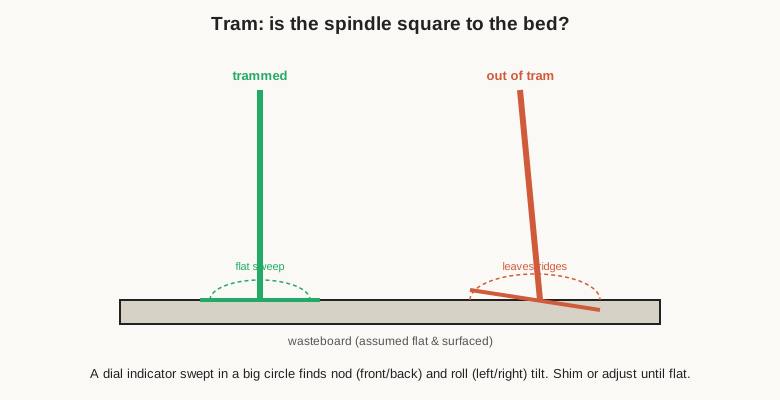
Tramming is making the spindle perpendicular to the bed. If the router is tilted even slightly — nodding forward-and-back or rolling side-to-side — a flat surfacing cut leaves faint ridges or scallops, and pockets come out with a sloped floor. Tramming is checked by sweeping a dial indicator mounted in the spindle in a wide circle over the bed and reading how the height changes across the sweep; the router is then shimmed or adjusted until the sweep reads flat. It is a fussy job done rarely, but a machine out of tram will disappoint on every surfacing and pocketing operation until it is fixed.
Squaring is making the X and Y axes truly perpendicular to each other, so a commanded rectangle comes out as a rectangle rather than a parallelogram. On a Shapeoko this is largely about the assembly of the gantry and the setting of the belts and eccentrics, and it is checked with the machine cutting or scribing a large test square and measuring its diagonals. Like tramming, it is set-and-forget until something is disturbed, but it underlies the dimensional accuracy of everything the machine does.
A practical note ties squaring and tramming together: they are worth checking whenever the machine is moved, after any hard crash or collision, and periodically as part of general upkeep, but they are emphatically not per-job chores. A machine that is square and trammed stays that way until something disturbs it, which is one more argument for the stable, permanent mounting a good cabinet provides — a machine that never gets nudged rarely goes out of square.
Surfacing the wasteboard is the third geometry task and the most routine. Because the machine’s accuracy depends on the bottom of the stock sitting on a surface that is flat relative to the machine’s own motion, the wasteboard is periodically skimmed flat by the machine itself: a large surfacing bit runs a raster pattern across the whole board, cutting it perfectly coplanar with the XY plane the machine moves in. After surfacing, the top of the wasteboard is, by definition, a true reference — and re-surfacing is how a chewed-up or slightly-off board is brought back to true. On the XXL’s large bed this takes a while, but it is the foundation of accurate work and of tricks like cutting all the way through thin stock without cutting into the machine.
5.6 Dust collection
Dust collection has been mentioned as an enclosure benefit; as an operating practice it deserves its own note. Beyond the health and housekeeping arguments, dust extraction directly improves the cut: chips left in the path get re-cut, which wastes cutting-edge life, adds heat, and worsens finish. A dust boot around the router, fed by a shop vacuum or dust extractor, clears chips as they are made and keeps the cut zone clean. It is one of those upgrades that pays for itself in bit life and part quality as much as in a cleaner shop, and on an enclosed machine it is what makes the enclosure a settling chamber rather than a dust box.
5.7 A realistic workflow, model to part
Pulling it together, a typical job on this machine runs roughly as follows. It begins in CAD/CAM — designing the part and generating toolpaths, choosing bits and feeds for each operation, and often simulating the result before any metal moves. The G-code is loaded into the sender (CNCjs on this machine), which is used to jog the router, set the work zero on the stock — by hand, or with a BitZero-style probe — and, for multi-tool jobs, to configure tool changes so each new bit is measured and offset correctly.
The stock is secured by whichever method suits it — clamps, tape-and-glue, or a fixture — with tabs planned wherever a through-cut would free a part. The router speed is set on its dial to suit the material and bit. A cautious operator does a dry run or an air-cut above the stock to confirm the toolpath is where it should be and nothing will collide, then starts the job for real, staying nearby — this is not a machine to leave unsupervised — watching and listening for the signs of a good cut and ready to stop if anything sounds wrong.
When the cutting finishes, the part is released — tabs cut, tape peeled, clamps removed — and finished by hand: sanding the tab stubs, deburring edges, and whatever the design calls for. Then the bed is cleaned, the wasteboard checked, and the machine readied for the next job. It is a rhythm that becomes second nature, and on a well-set-up, well-modified XXL it is a genuinely pleasant one. The final volume looks at what all this produces — the projects the machine is suited to — and collects the reference material: the full specification, the maintenance routine, and where to go to learn more.
Comments (0)