Shapeoko 3 XXL · Volume 4
The Modifications — Cabinet, Lead-Screw Z, and a Dedicated CNCjs PC
4.1 Three upgrades, one philosophy
A stock Shapeoko 3 XXL is a good machine; a well-modified one is a considerably better one, and the modifications that matter most are not exotic. They tend to be the same handful that the whole community converges on, because they each attack one of the machine’s understood weak points identified earlier in these volumes: the frame that likes to be kept flat, the belt Z that is the softest link in the motion chain, and the stock software-and-laptop control that ties up a computer and limits what the operator can automate.
This machine has received the three headline upgrades that together transform an open-frame belt router into a serious shop tool: a custom-built cabinet or enclosure, a lead-screw-driven Z axis in place of the stock belt Z, and a dedicated PC running CNCjs as the controller. This volume covers each one as a piece of general engineering — what problem it solves, how the conversion is done, what the options and trade-offs are — because those things are well understood and well documented. What it does not do is invent the specifics of the owner’s particular build. The exact cabinet design, the exact Z-axis hardware, and the exact CNCjs configuration are part of the owner’s own work and are being documented over time. Wherever those specifics belong, this volume leaves a clearly-marked slot and a note that the details are to come. The general engineering is solid ground; the owner’s parts and photos will fill in the particulars.
4.2 Modification one: the custom cabinet and enclosure
4.2.1 What problem it solves
A bare Shapeoko sitting on a workbench has four unglamorous problems, and a good cabinet addresses all of them at once.
The first is rigidity through the base. As established earlier, an extrusion frame holds its accuracy only when it sits flat, square, and unstressed. A wobbly bench, a twisted surface, or a machine that gets nudged around all quietly degrade the geometry. A purpose-built cabinet gives the machine a dead-flat, stiff, permanent home, ideally with the frame properly supported and levelled across its whole footprint rather than perched on whatever bench was handy. That alone improves repeatability.
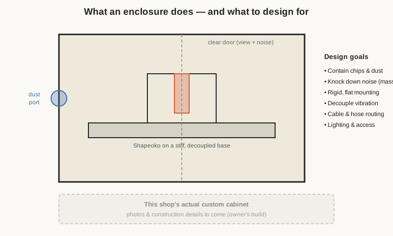
The second is dust and chips. A router throws a remarkable volume of fine dust and chips, and an open machine throws them across the entire shop. An enclosure contains that mess and gives dust collection somewhere to work from — a sealed volume with a single extraction point is dramatically easier to keep clean than an open machine in open air. For anyone cutting MDF or hardwood regularly, dust containment is not a luxury; the dust is both a nuisance and a genuine respiratory hazard.
The third is noise. A trim router spinning at 20,000-plus RPM, cutting hardwood, is loud — loud enough to be unpleasant and, over time, damaging to hearing. A well-built enclosure with mass in its walls can knock the perceived noise down substantially; community builds routinely report reductions on the order of 20 to 40 decibels, which is the difference between a machine you must wear ear protection near and one you can hold a conversation beside.
The fourth is simply integration and access: a cabinet gives a home to the controller, the computer, the dust hose, the wiring, lighting, and a screen, turning a sprawl of loose parts into one tidy, self-contained station.
4.2.2 The general engineering
The recurring lessons from good Shapeoko enclosure builds are consistent. Mass beats everything for noise: thick MDF or similar sheet (on the order of 18 to 25 millimetres) blocks far more sound than thin plywood, which tends to resonate and radiate noise rather than stop it. Sound is further managed with mass-loaded layers and absorptive lining, and with attention to the leaks — every gap, cable pass-through, and dust port is a path for noise to escape, so ventilation is best done through baffled or silenced routes rather than open holes.
For dust, a single well-placed extraction port in the sealed volume, paired with the router’s own dust boot where fitted, does most of the work; the enclosure turns the whole machine into a settling chamber that the extractor draws from. Viewing and access are usually handled with a clear polycarbonate or acrylic door — double-glazed with an air gap if noise is a priority — and interior lighting, because a machine you cannot see working is a machine you cannot supervise. And throughout, the design has to leave generous clearance beyond the machine’s already-large footprint for the gantry’s full travel, the cabling, and the dust hose, plus room to reach in and work.
Where a builder can go further than a simple box is in making the enclosure part of the machine’s rigidity and vibration story: mounting the Shapeoko to a stiff, flat internal base, decoupling that base from the outer shell so vibration is not transmitted and amplified, and integrating the whole thing at a comfortable working height. A cabinet done this way is not just a noise-and-dust box; it is a foundation that makes the machine cut better.
4.2.3 The owner’s build
The specific cabinet built for this machine — its materials and construction, how the Shapeoko is mounted and levelled inside it, the dust extraction and ventilation scheme, the door and lighting, the noise treatment, and how the controller and computer are integrated — is the owner’s own design and is being documented as photos and details are supplied. Details to come. The general principles above describe the class of solution; the particulars of this build will fill in against them.
4.3 Modification two: the lead-screw-driven Z axis
4.3.1 Why the belt Z is the axis worth changing first
Of all the modifications a Shapeoko owner can make, converting the Z axis is the one with the most direct effect on cut quality, and the reasons trace straight back to the belt-drive weaknesses covered earlier. The stock Shapeoko 3 Z axis is belt-driven, and a belt on a vertical axis is asked to do something belts are poor at: hold a heavy router against gravity while positioning it precisely. Three problems follow.
Backlash and softness. A belt is elastic. When the cutter plunges or the load changes, the belt stretches and the router’s actual height lags what the controller commanded, then springs back. The result is imprecise plunge depths and a Z that feels “spongy” under load — poor for anything needing consistent depth, and a limiting factor when trying to take heavier or more confident cuts.
Holding the weight. On the stock belt Z, the belt must continuously resist the router’s weight. Any belt stretch, and any tendency of the drive to give under cutting force, translates into the cutter creeping deeper than intended precisely when it is being pushed hardest — the worst possible time.
Rigidity. The stock Z carriage rides on V-wheels like the other axes, adding the same small, adjustable play. In the vertical axis, where plunge accuracy and resistance to deflection matter most, that softness is felt keenly.
A screw-driven Z addresses all three at once, which is why it is the near-universal first serious upgrade and why Carbide itself now ships screw-driven Z axes as standard on its newer machines.
4.3.2 The general engineering of a screw conversion
The core idea is to replace the belt with a lead screw (or a ball screw) and to replace the V-wheel guidance with linear rails. A rotating screw driven by the Z motor engages a nut fixed to the router carriage; as the screw turns, the nut — and the router with it — travels up or down. Compared with a belt, a screw is vastly stiffer, has far less give under load, and — critically — it holds position when the power is off, because the screw-and-nut geometry does not back-drive under the router’s weight. Linear rails replace the V-wheels with preloaded, ground guidance that removes the last of the play.
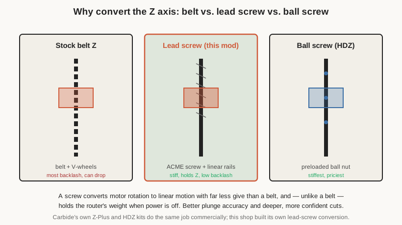
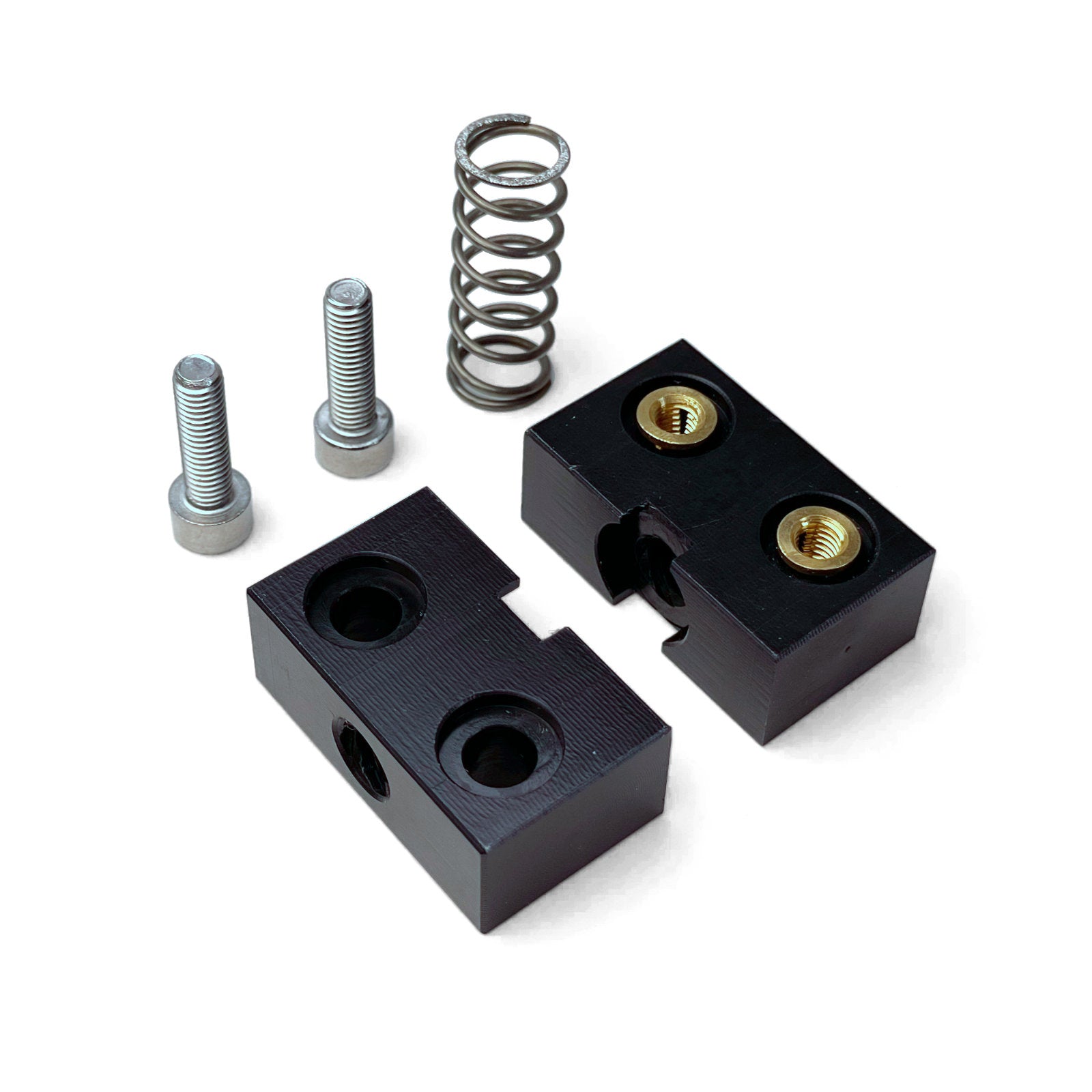
There are two flavours of screw. A lead screw — typically an ACME-profile trapezoidal thread — is the common, cost-effective choice. It converts rotation to linear motion simply and stiffly. Its one characteristic worth managing is backlash: the small lost motion when the screw reverses direction, because the nut has clearance on the thread. This is handled with an anti-backlash nut, usually a spring-loaded or split nut that takes up the slack and keeps the screw and nut in constant contact.
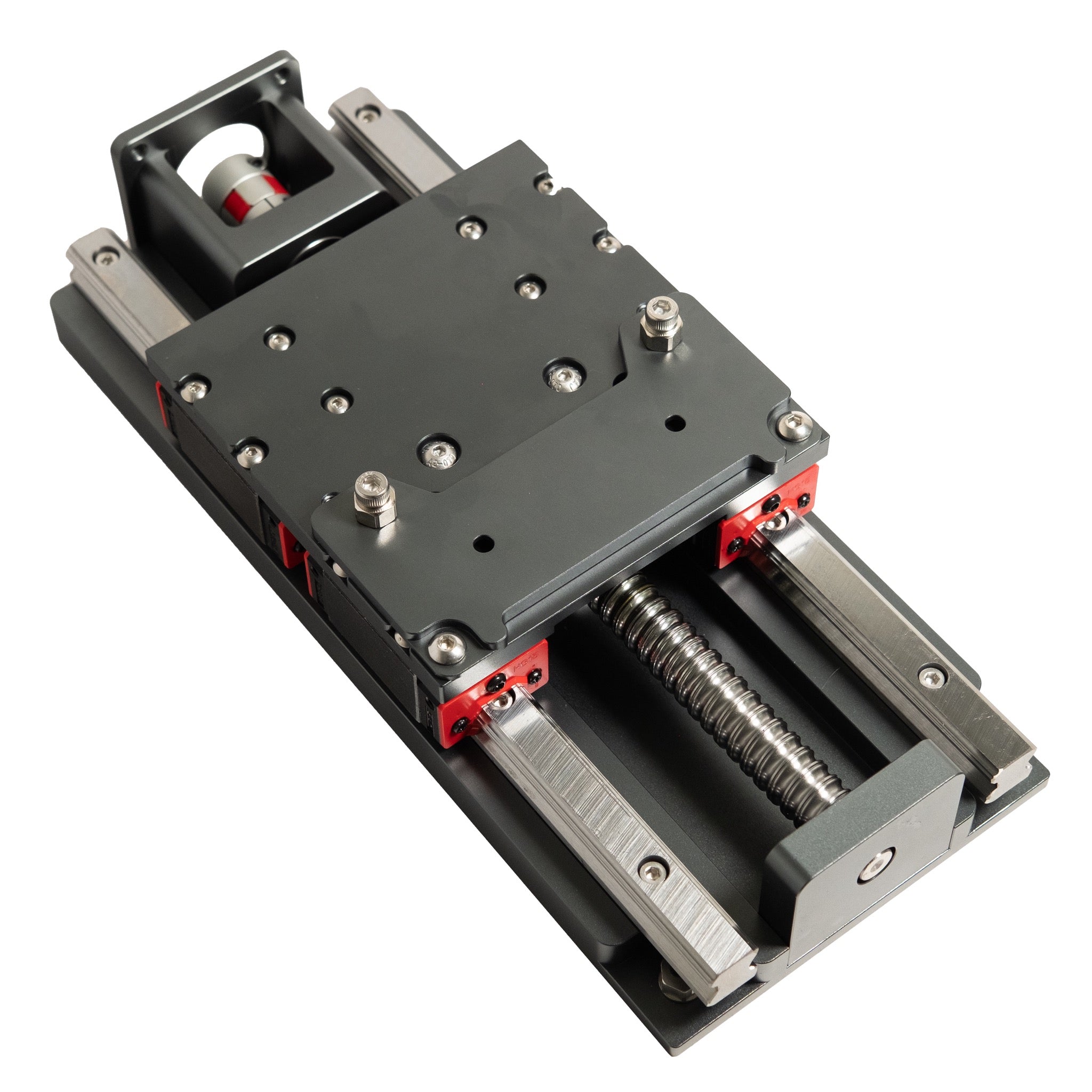
A ball screw goes further: instead of a plain nut sliding on the thread, recirculating ball bearings roll in the screw’s grooves, giving very low friction and — because the balls are preloaded — very little backlash and high stiffness. Ball screws are the premium option: stiffer and smoother, but more expensive and more involved to fit.
Carbide’s own commercial versions of this upgrade bracket the choice neatly. The Z-Plus kit replaces the belt-and-V-wheel Z with a lead screw and linear rails, delivering most of the rigidity benefit at a modest price. The HDZ (“Heavy-Duty Z”) kit uses a ball screw and linear rails, provides a longer travel (on the order of 150 millimetres) and enough rigidity to carry a heavy spindle, and costs correspondingly more. Both exist precisely because so many owners wanted exactly this conversion; a shop building its own lead-screw Z is walking the same road, tailored to its own parts and budget.
4.3.3 The firmware side of a Z conversion
A screw conversion is not purely mechanical. Because the relationship between motor rotation and vertical travel changes completely — a belt-and-pulley moves a fixed distance per revolution, a screw moves its pitch per revolution — the controller’s steps-per-millimetre for Z must be recalculated and rewritten into GRBL, along with revisiting the Z maximum feed and acceleration to suit the new mechanism. A lead screw typically moves the axis a shorter distance per motor revolution than a belt did, which makes the Z slower but finer and stronger. Getting that configuration right is as much a part of the conversion as the hardware, and it lives in the firmware layer described in the previous volume.
4.3.4 The owner’s build
The specific lead-screw Z conversion on this machine — the exact screw (pitch and type), the nut and anti-backlash arrangement, the linear rails and carriage, the motor coupling, and the recalculated GRBL configuration that goes with it — is the owner’s own build and is documented as those details are supplied. Details to come. The engineering above explains why the conversion was worth doing and how such a conversion works in general; the particulars of this machine’s Z will fill in against that background.
4.4 Modification three: the dedicated CNCjs PC
4.4.1 Why a dedicated controller
The reasoning behind moving from the stock Carbide Motion sender to CNCjs was set out in the controller-and-software volume, and the physical modification that goes with it is straightforward in concept: give the machine its own computer. Rather than plugging a laptop in for each session — tying up the laptop, and exposing a running job to the risk of a sleep timer, an update, or a closed lid — a dedicated computer lives with the machine and does nothing but run CNCjs and talk to the GRBL board.
4.4.2 The general patterns
Two hardware patterns dominate, and both work well.
The first is a Raspberry Pi (or similar single-board computer). A Pi is small, silent, cheap, and always-on, and CNCjs runs comfortably on it — indeed CNCjs is frequently cited as the best-networked GRBL interface specifically because it suits this always-on, browser-accessed, Pi-hosted role. A Pi with a small touchscreen bolted to the machine becomes a self-contained control panel, while the same interface remains reachable from any other device on the network.
The second is a mini-PC — a small x86 machine running Windows or Linux. It offers more headroom and a familiar desktop environment, at the cost of a little more size, noise, and power draw. Either way the shape is identical to the diagram in the software volume: a small dedicated computer running the CNCjs server, connected over USB serial to the original Carbide Motion GRBL board, and serving its interface to whatever screens the operator wants to use.
The payoff of this pattern is everything CNCjs offers — scripted macros for tool changes and probing, a toolpath visualiser, and multi-device network access so a job can be started at the machine and monitored from elsewhere — delivered by a controller that is always ready and never borrowed back for other work. And, as with the other modifications, it changes only the top of the stack: GRBL and the controller board underneath are untouched.
4.4.3 The owner’s build
The specific computer running CNCjs for this machine — whether a Raspberry Pi or a mini-PC, its operating system, its screen and mounting, and the exact macros and configuration set up for this machine’s tool changes, probing, and modified Z — is the owner’s own build and is documented as those details are supplied. Details to come. The general patterns above describe the class of solution; this machine’s particular controller will fill in against them.
4.5 The modified machine as a whole
Taken together, the three modifications reshape the machine along exactly the lines its stock design invites. The cabinet gives the extrusion frame the flat, stiff, quiet, dust-contained home it wants. The lead-screw Z replaces the softest link in the motion chain with a stiff, position-holding screw, sharpening plunge accuracy and allowing more confident cuts. The dedicated CNCjs PC turns control from a borrowed laptop into a permanent, scriptable, networked station. None of them fights the machine’s nature; each of them removes one of the specific limitations catalogued in the earlier volumes. The result is still, recognisably, a Shapeoko 3 XXL — but one built out to the edge of what the platform can comfortably become. The next volume turns from the machine itself to the craft of using it: how to hold work, choose bits, set feeds, keep everything square, and get from a model to a finished part.
Comments (0)